Engine heat dissipation system used for railway engineering mechanical vehicle

A technology of railway engineering and cooling system, applied in the direction of machine/engine, engine components, engine cooling, etc., can solve problems such as power drop, increased engine temperature, and influence on powertrain layout.

Pending Publication Date: 2021-05-28
CRCC HIGH TECH EQUIP CORP LTD
View PDF2 Cites 0 Cited by
  • Summary
  • Abstract
  • Description
  • Claims
  • Application Information

AI Technical Summary

Problems solved by technology

The invention can solve the problem that the engine radiator of the existing snow removal vehicle blows backward to dissipate heat at the same time, which increases the temperature of the subsequent engine, causing the power to

Method used


Image

  • Engine heat dissipation system used for railway engineering mechanical vehicle
  • Engine heat dissipation system used for railway engineering mechanical vehicle
  • Engine heat dissipation system used for railway engineering mechanical vehicle

Examples


Embodiment Construction

[0037] In order to more clearly illustrate the embodiments of the present invention or the technical solutions in the prior art, the following briefly introduces the drawings required for the description of the embodiments or the prior art. Apparently, the drawings in the following description are only some embodiments of the present invention, and those skilled in the art can obtain other embodiments according to these drawings without creative efforts.

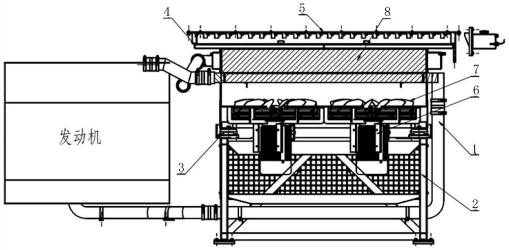
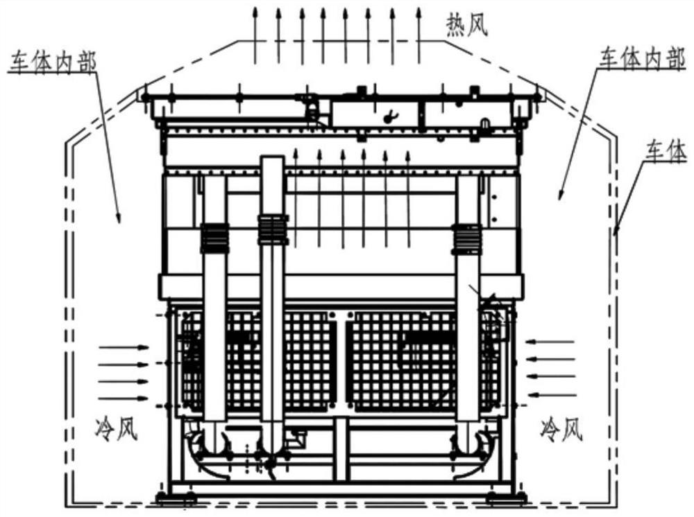
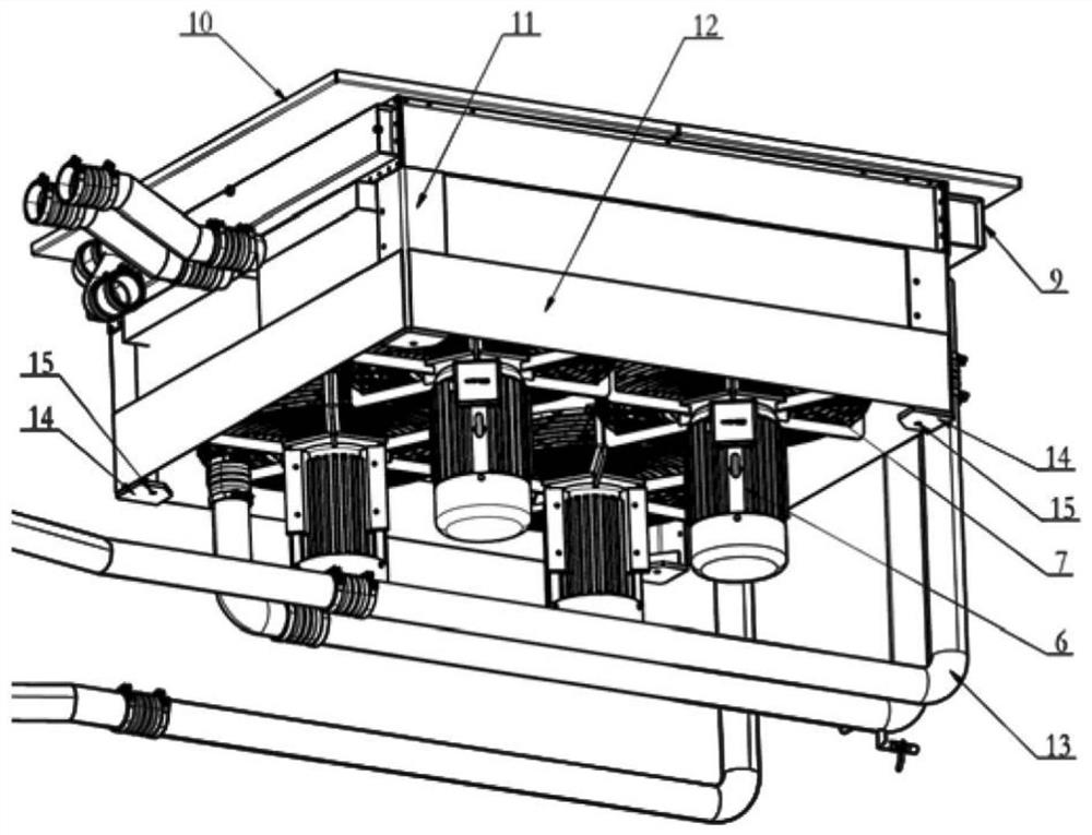
[0038] Such as figure 1As shown, a kind of engine cooling system for railway engineering machinery vehicle of the present invention comprises radiator assembly 1, bracket assembly 2 and movable shutter 5, and radiator assembly 1 is supported by bracket assembly 2, and described cooling The radiator assembly 1 includes a radiator frame 9, a motor 6, a radiator fan 7 and a radiator core 8. The radiator core 8 is horizontally arranged on the top of the radiator assembly 1. The arrangement can effectively compress the installati...


PUM


Abstract

The invention relates to an engine heat dissipation system used for a railway engineering mechanical vehicle. The engine heat dissipation system comprises a radiator assembly (1), a bracket assembly (2) and a movable shutter (5), wherein the radiator assembly (1) is supported by the bracket assembly (2); the radiator assembly (1) comprises a radiator framework (9), an electric motor (6), a heat dissipation fan (7) and a radiator core body (8) which is horizontally arranged on the top of the radiator assembly (1), so that floor space is saved; four asynchronous motors drive the heat dissipation fan (7) to dissipate heat for the radiator core body (8), and the heat dissipation fan (7) sucks air inside a vehicle body and then perpendicularly blows the air to the outside of a vehicle top after passing through the radiator core body (8), so that exchange between air inside the vehicle body and air outside the vehicle body can be effectively promoted, and hot air is prevented from being repeatedly sucked into the vehicle body.

Description

technical field [0001] The invention relates to the technical field of railway machinery, in particular to an engine cooling system for railway engineering machinery vehicles. Background technique [0002] At present, the radiators of the engine cooling systems of domestic railway engineering vehicles are mostly located at the rear end of the engine, and are arranged vertically, with two modes of blowing and suction. Among them, most of the blowing methods need to design an air guide device to guide the hot air blown out of the radiator to the outside of the car body and eliminate it. Most of the suction methods need to consider the air intake requirements of the radiator, and reserve a certain air intake space at the front end of the radiator. The above two methods need to occupy a large installation space no matter the design of the air guiding device or the reservation of the air intake space, which in turn affects the layout of the entire power transmission system. [0...

Claims


Application Information

Patent Timeline
IPC IPC(8): F01P11/00F01P5/04E06B7/086
CPCE06B7/086F01P5/04F01P11/00F01P2005/046
Inventor 刘飞香张宝明黄鹏李家德王运祥梁清帅戌月升
Owner CRCC HIGH TECH EQUIP CORP LTD
Why Eureka
Try Eureka