Internal-power-driven compact power system for high-speed-ratio pump

A technology of power system and large speed ratio, which is applied in the field of compact power system for large speed ratio pumps, can solve the problems of unrealizable, easy to pollute oil, high or low speed, etc., so as to reduce space occupation and save energy. The effect of installation space and large speed-up ratio

Pending Publication Date: 2021-05-28
SHANGHAI TIANDI MINING EQUIP TECH CO LTD +2
View PDF0 Cites 0 Cited by
  • Summary
  • Abstract
  • Description
  • Claims
  • Application Information

AI Technical Summary

Problems solved by technology

But the ultra-thin seam shearer, especially the ultra-thin coal seam shearer with suspended body structure, in order to improve the adaptability of the shearer to the roof, floor and mining environment, it is necessary to shorten the span between the left and right drums as much as possible. If the independent hydraulic system is still set in the traditional way, it may not be realized, or it may affect the layout of the overall structure of the shearer, such as causing difficulties in the layout of other components, and at the same time reducing the adaptability of the shearer
[0003] There are also power systems in the industry that use the main transmission system to provide power for the gear pump in an independent oil tank. On the one hand, the gear pump is connected to the pipeline and installed in the oil tank, which is easy to contaminate the oil during maintenance and disassembly. On the other hand, due to the main transmission With different settings of the system speed ratio, the output speed to the gear pump may be high or low, which is uncertain, and may not be able to meet the needs of the input speed of the gear pump, nor may it meet the requirements of compact space layout

Method used


Image

  • Internal-power-driven compact power system for high-speed-ratio pump
  • Internal-power-driven compact power system for high-speed-ratio pump
  • Internal-power-driven compact power system for high-speed-ratio pump

Examples


Embodiment Construction

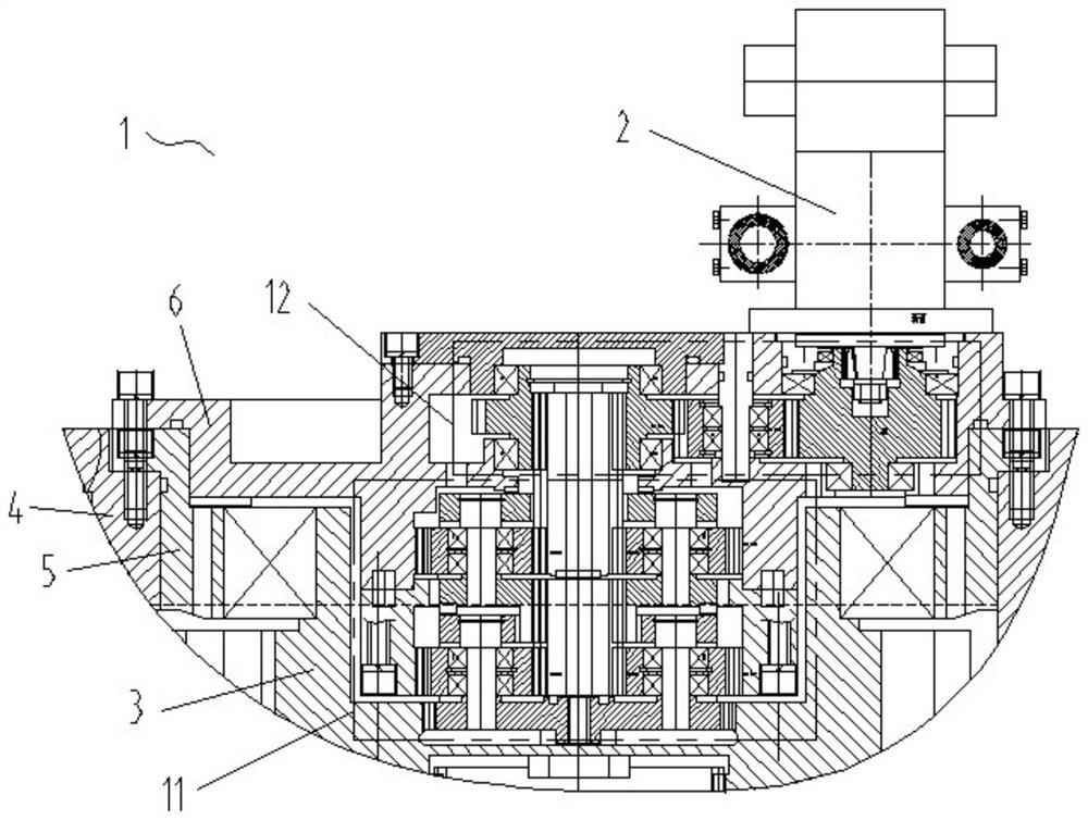
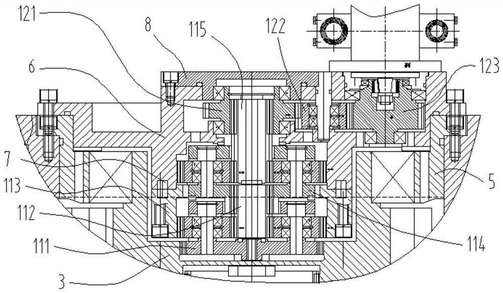
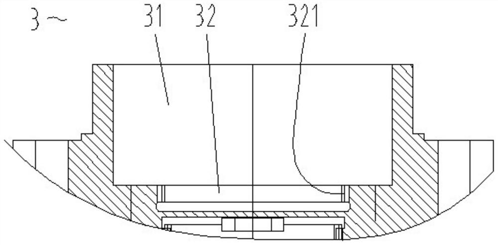
[0033] The invention discloses a compact power system 1 for a pump with a large speed ratio driven by internal power (which may be referred to simply as a compact power system for a pump), which can be used to provide power for a gear pump 2 of a hydraulic system of a coal mining machine, and can replace Conventional pump motor. Such as Figure 1-5 As shown, the pump compact power system includes a two-stage series planetary speed-up mechanism 11 and a one-stage fixed-shaft gear speed-up mechanism 12 that are sequentially connected by transmission. The power input end and the power output end of the two-stage series planetary speed-up mechanism are respectively the planet carrier 111 of the first-stage planetary mechanism and the sun gear 115 of the second-stage planetary mechanism. The power input end and the power output end of the first-stage fixed axis gear speed-up mechanism are the head gear 121 and the end gear 123 respectively. The planet carrier of the first-stage p...


PUM


Abstract

The invention relates to an internal-power-driven compact power system for a high-speed-ratio pump. The internal-power-driven compact power system comprises a two-stage serial planetary speed increasing mechanism and a one-stage fixed-shaft gear speed increasing mechanism which are sequentially in transmission connection; the power input end and the power output end of the two-stage serial planetary speed increasing mechanism are a planet carrier of a first-stage planetary mechanism and a sun gear of a second-stage planetary mechanism respectively, and the power input end and the power output end of the first-stage fixed shaft gear speed increasing mechanism are a head end gear and a tail end gear respectively; and a planet carrier of the first-stage planetary mechanism is in spline connection with a fixed shaft gear in a main transmission system, the sun gear of the second-stage planetary mechanism is in spline connection with the head end gear, and a gear pump transmission shaft installation connector structure is arranged on the core portion of the tail end gear. Power of the internal-power-driven compact power system comes from a cutting transmission system, the structure is compact, the speed is stable, and the overall layout requirement of a thin or ultra-thin coal seam coal mining machine of a suspended machine body structure can be met.

Description

technical field [0001] The invention relates to a compact power system for a high-speed-ratio pump driven by internal power, which is suitable for a thin or extremely thin coal seam shearer, especially a thin or extremely thin coal seam shearer with a suspended body structure. Background technique [0002] A separate pump motor is usually used as the power source of the hydraulic system in a coal shearer, and the pump motor and valve group are installed in an independent oil tank at the same time to form an independent hydraulic system. But the ultra-thin seam shearer, especially the ultra-thin coal seam shearer with suspended body structure, in order to improve the adaptability of the shearer to the roof, floor and mining environment, it is necessary to shorten the span between the left and right drums as much as possible. If the independent hydraulic system is still set in the traditional way, it may not be realized, or it may affect the layout of the overall structure of ...

Claims


Application Information

Patent Timeline
IPC IPC(8): F16H57/02F16H57/021F16H57/023F16H57/08E21C31/02
CPCE21C31/02F16H57/02F16H57/021F16H57/023F16H57/08F16H2057/02069F16H2057/02086
Inventor 章立强周常飞宋相坤王振乾郭岱宋振董超胡滔胡璟顾恩洋丁海春张斌刘凯朱信平胡俊王广张晓永吴振毅林杭王兆胜李辉贾思然
Owner SHANGHAI TIANDI MINING EQUIP TECH CO LTD
Why Eureka
Try Eureka