
Transmission gear selecting and shifting row fixing mechanism

A technology for shifting gears and transmissions. It is applied to mechanical equipment, components with teeth, belts/chains/gears, etc., and can solve problems such as poor shifting feel, uneven shifting force, and difficult to control the shape and line. , to achieve the effect of benefiting quality and consistency control, improving gear shifting comfort, and improving gear selection and shifting performance.

Inactive Publication Date: 2021-05-28
SAIC-GM-WULING AUTOMOBILE CO LTD
View PDF6 Cites 2 Cited by
  • Summary
  • Abstract
  • Description
  • Claims
  • Application Information

AI Technical Summary

Problems solved by technology

[0003] 1. The shape lines of the gear selection and shifting are combined together, and the shape lines are not easy to control, resulting in uneven selection and shifting force, gear shifting stuck, and poor shifting feel;
[0004] 2. The gear shift and fixed row shape line adopts the gear shift M head 3, and the gear shift stroke limit is fixed. The shifting of the gear gear is transmitted to the shift fork through the synchronizer gear sleeve, and then transmitted to the shift handle through the gear shift operating mechanism. Cause the gear shift handle to vibrate and shake hands; when the size is not well controlled, it is easy to cause the transmission to go out of gear due to insufficient initial stroke

Method used


Image

  • Transmission gear selecting and shifting row fixing mechanism
  • Transmission gear selecting and shifting row fixing mechanism
  • Transmission gear selecting and shifting row fixing mechanism

Examples


Embodiment Construction

[0021] The following will clearly and completely describe the technical solutions in the embodiments of the present invention with reference to the accompanying drawings in the embodiments of the present invention. Obviously, the described embodiments are only part of the embodiments of the present invention, not all of them. Based on the embodiments of the present invention, all other embodiments obtained by persons of ordinary skill in the art without creative efforts fall within the protection scope of the present invention.

[0022] It should be noted that if there is a directional indication (such as up, down, left, right, front, back...) in the embodiment of the present invention, the directional indication is only used to explain the position in a certain posture (as shown in the accompanying drawing). If the specific posture changes, the directional indication will also change accordingly.

[0023] In addition, if there are descriptions involving "first", "second" and ...


PUM


Abstract

The invention discloses a transmission gear selecting and shifting row fixing mechanism which comprises a gear selecting and shifting shaft, a cam, a gear selecting row fixing pin and a gear shifting row fixing pin. The cam is installed on the gear selecting and shifting shaft, a gear selecting row fixing line and a gear shifting row fixing line are separately arranged on the cam, the gear selecting row fixing pin can move on the gear selecting row fixing line, and the gear selecting row fixing pin can move on the gear shifting row fixing line. The transmission gear selecting and shifting row fixing mechanism further comprises a control cover, the gear selecting and shifting shaft is installed on the control cover, and the gear selecting and shifting shaft can axially move or rotate relative to the control cover. According to the transmission gear selecting and shifting row fixing mechanism, the problems of uneven gear selecting / shifting force of a transmission, gear shifting clamping stagnation, gear shifting handle shaking, transmission out-of-gear and the like can be effectively solved, the gear selecting and shifting performance of the manual transmission is improved, and the gear shifting comfort is improved; and the gear selecting row fixing line and the gear shifting row fixing line are separately designed, so that the structure control is simpler, and the quality and consistency control of gear selecting and shifting cam parts is facilitated.

Description

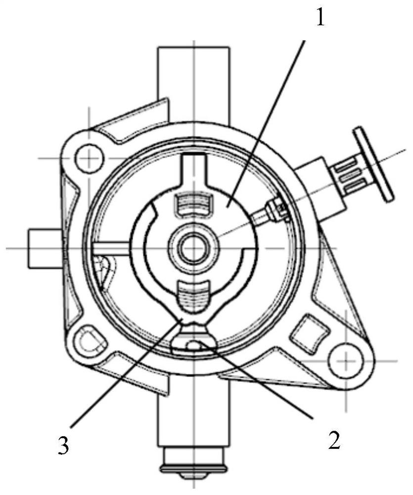
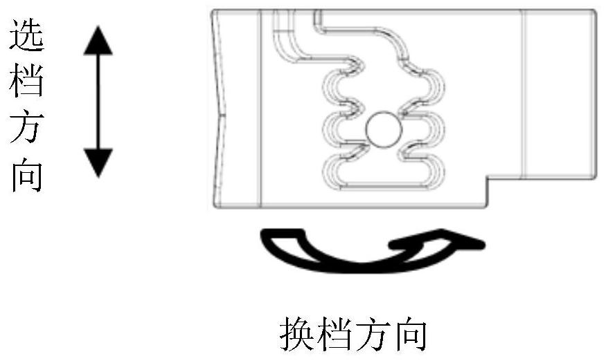
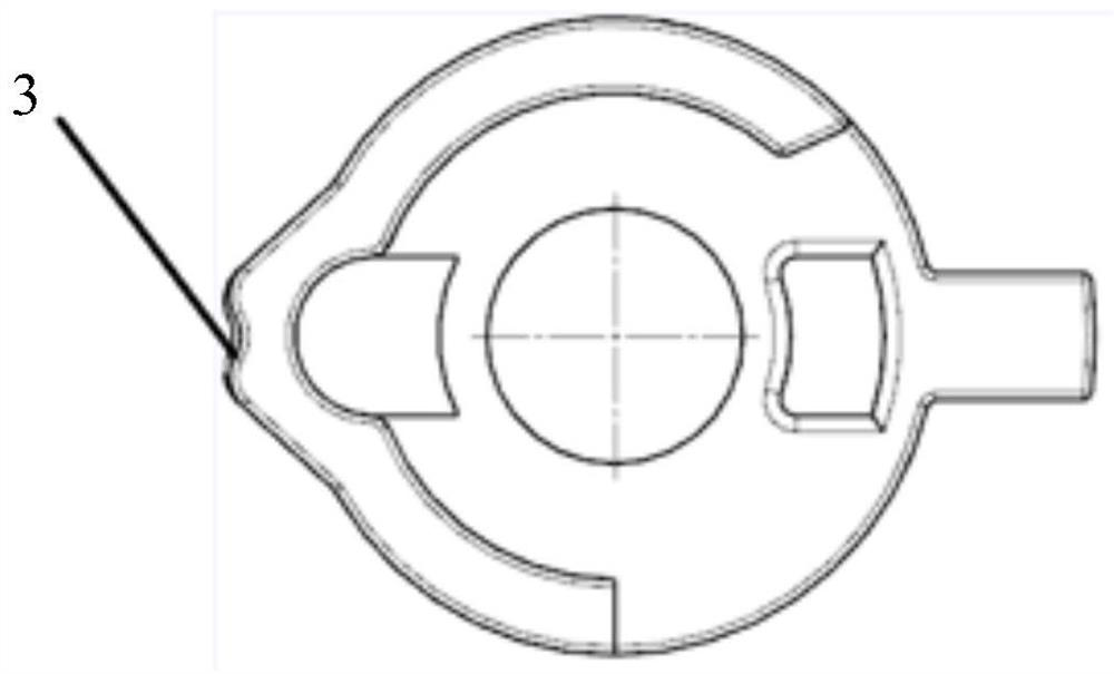
technical field [0001] The invention relates to the technical field of transmissions, in particular to a gear selection, shifting and scheduling mechanism of a transmission. Background technique [0002] The shifting structure of the manual transmission of the developed vehicle type has been developed at present, and the shifting and shifting mechanism is designed on the cam 1 of the transmission control mechanism, and the shifting and shifting adopt the same fixed pin 2 (such as figure 1 shown), and the gear shift fixed row shape line adopts the gear shift M head 3 (such as figure 2 shown). When performing a gear selection operation, the cam 1 moves up and down, and the fixed row pin 2 acts on the center slot of the shift fixed row shape line. perform shifting maneuvers (such as image 3 When shown), the cam 1 rotates, and the fixed row pin 2 acts on the groove lines on both sides of the fixed row shape line for shifting, and the shifting performance is controlled by ch...

Claims


Application Information

Patent Timeline
Patent Type & Authority Applications(China)
IPC IPC(8): F16H59/02F16H61/24
CPCF16H59/02F16H61/24F16H2061/243
Inventor 吴昌兵王光良黄德健
Owner SAIC-GM-WULING AUTOMOBILE CO LTD
Learn More