
Cable fault positioning system and method

A fault location and cable technology, which is applied in the direction of fault location, fault detection according to conductor type, etc., can solve problems such as measurement failure and space constraints

Inactive Publication Date: 2021-05-28
GUANGDONG POWER GRID CO LTD +1
View PDF9 Cites 3 Cited by
  • Summary
  • Abstract
  • Description
  • Claims
  • Application Information

AI Technical Summary

Problems solved by technology

At present, the current detector commonly used in leakage current measurement is a fully enclosed Rogowski coil detector. During measurement, it is required to put the measuring coil on one end of the object to be measured (such as wires, cables, etc.), and the detector cannot be placed on the When the wire is on the wire, the measurement cannot be carried out; in addition, the clamp ammeter can also be used to directly clamp on the cable without passing through the cable end. However, for concealed cables inside the wall and underground, the two leakage Detection methods are limited by space

Method used


Image

  • Cable fault positioning system and method
  • Cable fault positioning system and method
  • Cable fault positioning system and method

Examples


Embodiment Construction

[0033] The present invention will be further described in detail below in conjunction with the accompanying drawings and embodiments. It should be understood that the specific embodiments described here are only used to explain the present invention, but not to limit the present invention. In addition, it should be noted that, for the convenience of description, only some structures related to the present invention are shown in the drawings but not all structures.

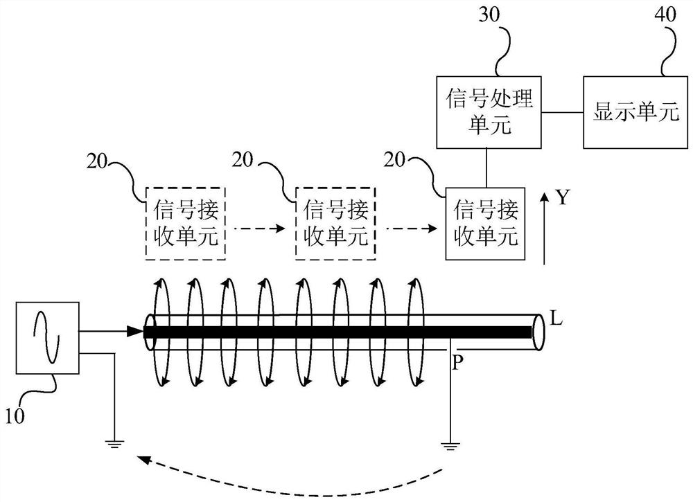
[0034] An embodiment of the present invention provides a cable fault location system, figure 1 It is a structural schematic diagram of a cable fault location system provided by an embodiment of the present invention, refer to figure 1 ,include:

[0035] A signal generator 10, the signal generator 10 is electrically connected to the cable L to be detected, and the signal generator 10 is used to transmit an electrical signal to the cable L to be detected;

[0036] A signal receiving unit 20, the signal receiving u...


PUM


Abstract

The embodiment of the invention discloses a cable fault positioning system and method. The system comprises: a signal generator electrically connected with a to-be-detected cable and used for transmitting an electric signal to the to-be-detected cable; a signal receiving unit used for sensing an electric signal on the to-be-detected cable along the extension track of the to-be-detected cable and generating a fault detection signal according to the electric signal; a signal processing unit electrically connected with the signal receiving unit and used for amplifying and filtering the fault detection signal; and a display unit electrically connected with the signal processing unit and used for displaying the waveform of the fault detection signal so as to indicate the electric leakage position of the to-be-detected cable according to the strength of the fault detection signal. According to the technical scheme provided by the embodiment of the invention, the fault position of the concealed cable is determined, and the fault detection efficiency is improved.

Description

technical field [0001] The embodiments of the present invention relate to the technical field of power detection, and in particular to a cable fault location system and method. Background technique [0002] With the insulation aging of cables or electrical equipment, improper management or maintenance, and accidents, the insulation level of the power distribution system may be damaged, or the insulation level of electrical equipment may decline, which is not conducive to the normal production work, and eventually leads to There is a leakage fault in the cable. [0003] The most important thing to solve the leakage fault in the low-voltage station area is to quickly locate the location of the leakage fault. Only when the fault point of the leakage can be found in time, the maintenance personnel of the power supply station can repair the leakage fault in time and restore the power supply capacity as soon as possible. At present, the current detector commonly used in leakage c...

Claims


Application Information

Patent Timeline
IPC IPC(8): G01R31/08
CPCG01R31/083
Inventor 林志超张俊岭罗步升丘桢坤陈参宁宋志坚徐大勇薛永端吴旭灿
Owner GUANGDONG POWER GRID CO LTD
Learn More