Optical device

A technology of optical devices and optical waveguides, applied in instruments, optics, nonlinear optics, etc., can solve the problems of high heating power consumption of heating electrodes and poor performance of optical devices

Inactive Publication Date: 2021-05-28
INST OF MICROELECTRONICS CHINESE ACAD OF SCI
View PDF5 Cites 0 Cited by
  • Summary
  • Abstract
  • Description
  • Claims
  • Application Information

AI Technical Summary

Problems solved by technology

[0003] However, in the process of heating the optical waveguide through the heating electrode in the existing optical device, the heating power consumption of the heating electrode is relatively large, which makes the working performance of the optical device poor

Method used


Image

  • Optical device
  • Optical device
  • Optical device

Examples


Embodiment Construction

[0020] The following will clearly and completely describe the technical solutions in the embodiments of the present invention with reference to the accompanying drawings in the embodiments of the present invention. Obviously, the described embodiments are only some, not all, embodiments of the present invention.

[0021] Various schematic views of embodiments of the invention are shown in the drawings, which are not drawn to scale. Therein, certain details have been exaggerated and certain details may have been omitted for the sake of clarity. The shapes of the various regions and layers shown in the figure, as well as their relative sizes and positional relationships are only exemplary, and may deviate due to manufacturing tolerances or technical limitations in practice, and those skilled in the art will Regions / layers with different shapes, sizes, and relative positions can be additionally designed as needed.

[0022] Hereinafter, the terms "first", "second", etc. are used ...


PUM

PropertyMeasurementUnit
radiusaaaaaaaaaa

Abstract

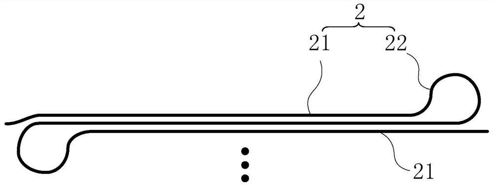
The invention discloses an optical device, and relates to the technical field of optical devices. The optical device is used for reducing the heating power consumption when a heating electrode heats an optical waveguide so as to improve the working performance of the optical device. The optical device comprises a substrate, the optical waveguide and the heating electrode, wherein the optical waveguide and the heating electrode are formed in the substrate; the optical waveguide is a snake-shaped optical waveguide and comprises a plurality of first waveguide parts and at least one second waveguide part; the plurality of first waveguide parts are distributed in the substrate along the width direction of the optical waveguide; every two adjacent first waveguide parts are connected through the corresponding second waveguide part; the heating electrode is located above the multiple first waveguide parts, the length of the heating electrode is smaller than or equal to the maximum length of the multiple first waveguide parts, and the heating electrode is used for heating the multiple first waveguide parts.

Description

technical field [0001] The invention relates to the technical field of optical devices, in particular to an optical device. Background technique [0002] The heating electrode is one of the very important components in optical devices. Specifically, when the heating electrode is energized, it can heat the optical waveguide located under the heating electrode. Based on the thermo-optic effect, the optical properties (such as the refractive index) of the heated optical waveguide will change, so as to realize the tuning of the transmission signal in the optical waveguide. [0003] However, in the process of heating the optical waveguide through the heating electrode in the existing optical device, the heating power consumption of the heating electrode is relatively large, so that the working performance of the optical device is poor. Contents of the invention [0004] The object of the present invention is to provide an optical device, which is used to reduce the heating po...

Claims


Application Information

Patent Timeline
Patent Type & Authority Applications(China)
IPC IPC(8): G02F1/01
CPCG02F1/0147G02F1/011G02F1/0102
Inventor 杨妍
Owner INST OF MICROELECTRONICS CHINESE ACAD OF SCI
Why Eureka
Try Eureka