Supercharge Your Innovation With Domain-Expert AI Agents!

Array antenna and device

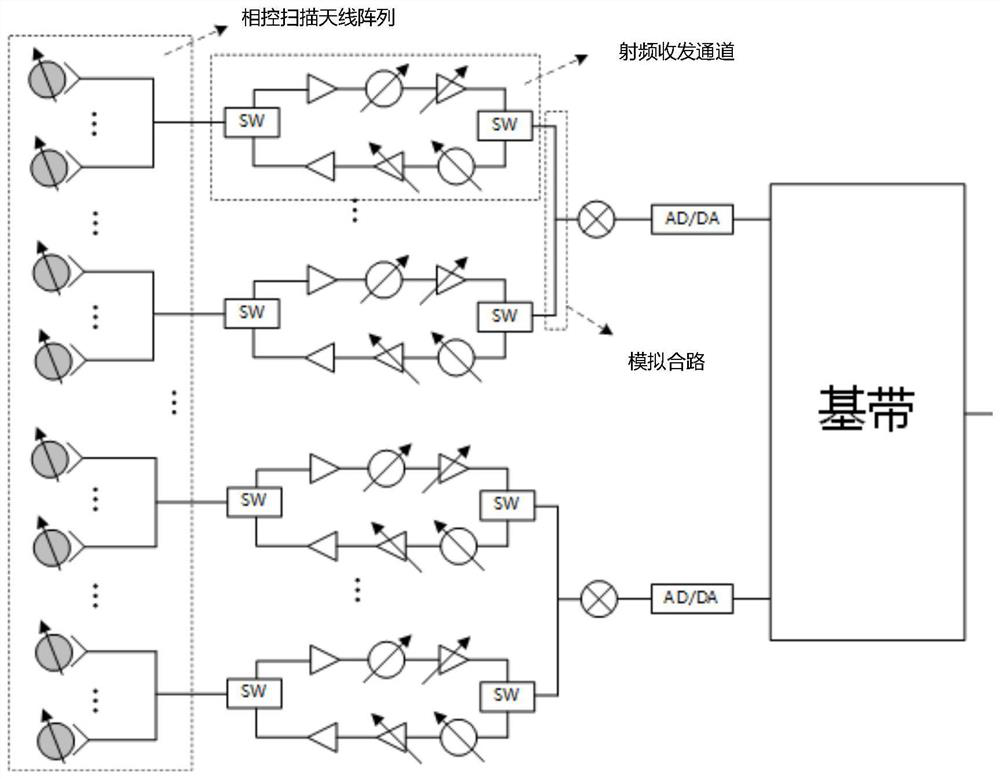
An array antenna and antenna technology, applied in antennas, antenna arrays, specific array feeding systems, etc., can solve problems such as high profile, small vertical scanning angle, and difficulty in meeting the requirements of 5G high-frequency base station antenna systems

Active Publication Date: 2021-05-28
SHANGHAI HUAWEI TECH CO LTD
View PDF16 Cites 2 Cited by
  • Summary
  • Abstract
  • Description
  • Claims
  • Application Information

AI Technical Summary

Problems solved by technology

[0003] The main problems of existing passive phased array antenna solutions are high profile, large volume, and small vertical scanning angle (generally less than ±10°), which makes it difficult to meet the system requirements of 5G high-frequency base station antennas

Method used


Image

  • Array antenna and device
  • Array antenna and device
  • Array antenna and device

Examples


Embodiment Construction

[0029] The following will clearly and completely describe the technical solutions in the embodiments of the application with reference to the drawings in the embodiments of the application. Apparently, the described embodiments are only some of the embodiments of the application, not all of them. Based on the embodiments in this application, all other embodiments obtained by those skilled in the art without making creative efforts belong to the scope of protection of this application.

[0030]The terms "first", "second" and the like in the specification and claims of the present application and the above drawings are used to distinguish similar objects, and are not necessarily used to describe a specific sequence or sequence. It is to be understood that the terms so used are interchangeable under appropriate circumstances such that the embodiments described herein can be practiced in sequences other than those illustrated or described herein. Furthermore, the terms "comprising...


PUM


Abstract

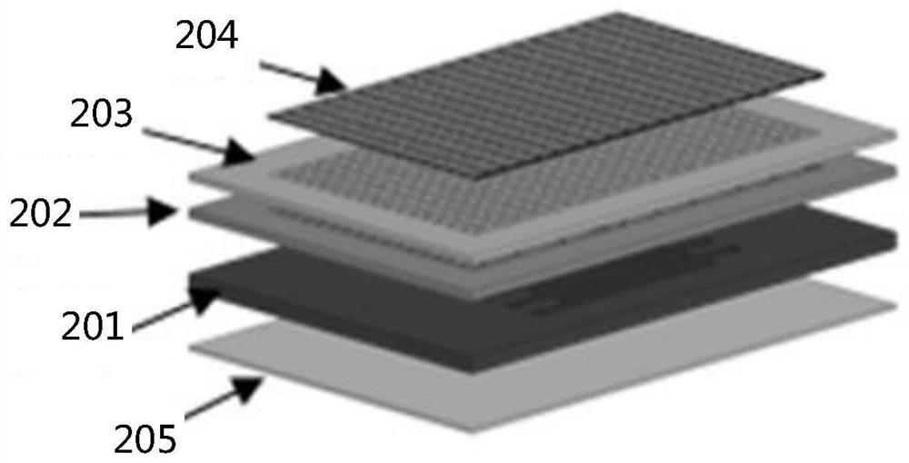
The invention discloses an array antenna, which comprises a first metal layer, a second metal layer, a third metal layer and a dielectric substrate, and is characterized in that the first metal layer receives a radio frequency signal and divides the radio frequency signal into a plurality of sub-signals through a plurality of waveguide power dividers, the second metal layer is a metal waveguide and is used for transmitting the sub-signals to corresponding radiation antenna sub-arrays, radiation units in the plurality of radiation antenna sub-arrays arranged on the third metal layer radiate the sub-signals outwards, and a plurality of phase shift antennas arranged on the dielectric substrate perform phase shift processing on the signals radiated by each radiation unit and radiate the signals outwards again. Through the technical scheme provided by the invention, the array antenna can realize beam scanning through a structure formed by laminating and combining the first metal layer, the second metal layer, the third metal layer and the dielectric substrate, and meanwhile, the array antenna with the laminated structure has the characteristics of low profile, easiness in assembly, low insertion loss and large scanning angle.

Description

technical field [0001] The present application relates to the technical field of communications, and in particular to an array antenna and equipment. Background technique [0002] In the 5th generation mobile communication technology (5G), in order to improve the coverage of the 5G high-frequency base station, the RF front-end is required to increase the peak effective isotropic radiated power (EIRP), and the antenna is required to have Beam scanning capability. Compared with active phased array antennas, passive phased array antennas have more advantages in terms of cost and power consumption, so beam scanning through passive phase shifting is an important technical direction. [0003] The main problems of existing passive phased array antenna solutions are high profile, large volume, and small vertical scanning angle (generally less than ±10°), which are difficult to meet the system requirements of 5G high-frequency base station antennas. How to reduce the profile of the...

Claims


Application Information

Patent Timeline
IPC IPC(8): H01Q21/00H01Q1/50H01Q3/24
CPCH01Q21/0006H01Q1/50H01Q3/24H01Q21/00H01P5/12H01P1/20Y02D30/70
Inventor 梁彬王伟锋彭杰王文涛
Owner SHANGHAI HUAWEI TECH CO LTD
Features
  • R&D
  • Intellectual Property
  • Life Sciences
  • Materials
  • Tech Scout
  • Unparalleled Data Quality
  • Higher Quality Content
  • 60% Fewer Hallucinations
Learn More