Novel high-voltage switch cabinet convenient to transfer and use method thereof

A high-voltage switchgear, a new type of technology, applied in substation/switch layout details, electrical components, substation/distribution device enclosures, etc., can solve problems such as easy damage, poor protection of high-voltage switchgear, and inconvenience to switch the state of use.

Pending Publication Date: 2021-05-28
张会娟
View PDF1 Cites 1 Cited by
  • Summary
  • Abstract
  • Description
  • Claims
  • Application Information

AI Technical Summary

Problems solved by technology

The anti-water high-voltage switchgear is provided with a drainage groove, a base and a first support rod, and the drainage groove, the base and the first support rod are arranged to prevent rainwater from entering the high-voltage switchgear shell and damaging the electrical appliances, but the following problems still exist: 1. .The structure of the high-voltage switchgear is fixed, it is not convenient to switch the use state, it is inconvenient to transfer the position, and it is time-consuming and laborious to use; 2. The protection effect of the high-voltage switchgear itself is poor, and it is easy to be damaged; 3. The shock absorption effect is poor, and the movement vulnerable to damage in the process

Method used


Image

  • Novel high-voltage switch cabinet convenient to transfer and use method thereof
  • Novel high-voltage switch cabinet convenient to transfer and use method thereof
  • Novel high-voltage switch cabinet convenient to transfer and use method thereof

Examples


Embodiment Construction

[0027] The following will clearly and completely describe the technical solutions in the embodiments of the present invention with reference to the accompanying drawings in the embodiments of the present invention. Obviously, the described embodiments are only some, not all, embodiments of the present invention.

[0028] Unless otherwise defined, the technical terms or scientific terms used herein shall have the usual meanings understood by those skilled in the art to which the present invention belongs. "First", "second" and similar words used in the patent specification and claims of the present invention do not indicate any order, quantity or importance, but are only used to distinguish different components. Likewise, words like "a" or "one" do not denote a limitation in quantity, but indicate that there is at least one.

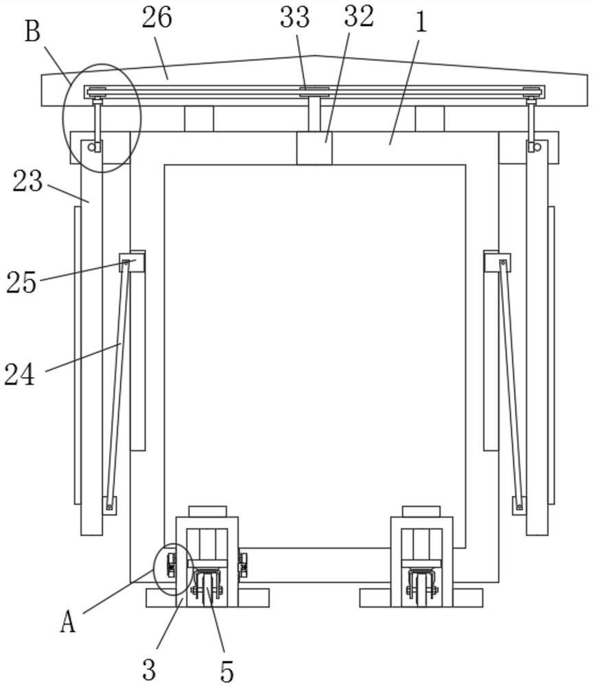
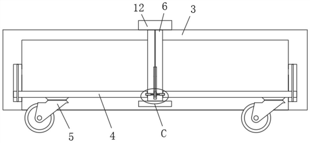
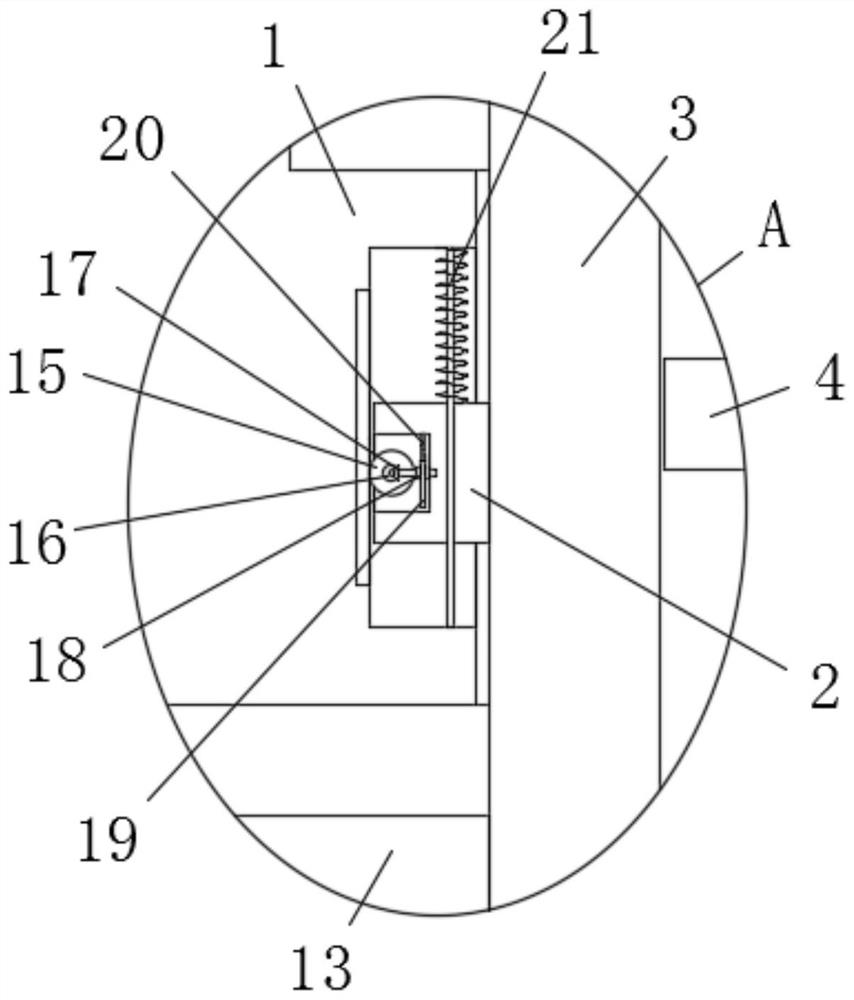
[0029] refer to Figure 1-5, a new type of high-voltage switchgear that is convenient to transfer, including a high-voltage switchgear body 1, two movin...


PUM


Abstract

The invention belongs to the field of high-voltage switch cabinets, particularly relates to a novel high-voltage switch cabinet convenient to transfer and a use method thereof, and aims to solve the problems that an existing high-voltage switch cabinet is fixed in structure, inconvenient to switch use states, inconvenient to transfer, time-consuming and labor-consuming to use, poor in protection effect and easy to damage. According to the technical scheme, the high-voltage switch cabinet comprises a high-voltage switch cabinet body, wherein two moving holes are formed in the bottom of the high-voltage switch cabinet body, supporting seats are installed in the two moving holes in a sliding mode, supporting plates are fixedly installed on the two sides of each supporting seat, control grooves are formed in the bottoms of the two supporting seats, and adjusting plates are installed in the two control grooves in a sliding mode. The high-voltage switch cabinet is reasonable in structure, convenient to operate, flexible in structure and convenient to switch use states, so that position transfer is convenient, time and labor are saved during use, the protection effect of the high-voltage switch cabinet is good, and the high-voltage switch cabinet is not prone to being damaged.

Description

technical field [0001] The invention relates to the technical field of high-voltage switchgear, in particular to a novel high-voltage switchgear that is convenient to transfer and its use method. Background technique [0002] High-voltage switchgear refers to the role of on-off, control or protection in the power generation, transmission, distribution, power conversion and consumption of power systems. The switchgear has functions such as overhead incoming and outgoing lines, cable incoming and outgoing lines, and bus connection. Various fields such as power plants, substations, petrochemicals, metallurgical steel rolling, light industry and textiles, factories and mines, residential quarters, high-rise buildings, etc. [0003] The prior art publication No. CN210246008U provides a high-voltage switchgear for anti-water accumulation, including the ground and a water level sensor, the ground is provided with a drainage groove, and the upper side of the ground is fixed with a b...

Claims


Application Information

Patent Timeline
Patent Type & Authority Applications(China)
IPC IPC(8): H02B1/54H02B1/52H02B1/50H02B1/28H02B1/30H02B1/32
CPCH02B1/28H02B1/303H02B1/306H02B1/32H02B1/505H02B1/52H02B1/54
Inventor 张会娟
Owner 张会娟
Why Eureka
Try Eureka