Sealed well-type garbage landfill gas emission structure

A gas emission and garbage dump technology, which is applied in the fields of landfill technology, drainage structures, solid waste removal, etc. It can improve the groundwater and air quality around the landfill site, prevent the impact of the ecological environment, and easily manage and control the spillage.

Active Publication Date: 2021-06-01
NANJING YUZHI INTELLIGENT TECH CO LTD
View PDF10 Cites 2 Cited by
  • Summary
  • Abstract
  • Description
  • Claims
  • Application Information

AI Technical Summary

Problems solved by technology

[0004] However, there are still obvious defects in the above-mentioned vertical circulation landfill structure of domestic waste: 1. The above-mentioned landfill adopts the traditional open-air layered soil-covered landfill method to process garbage, and the open-type layered soil-covered landfill method Although the cost of burial is low, the covered soil cannot be completely compacted by mechanical rolling, so it cannot prevent the overflow of landfill gas, because landfill gas contains about 50% methane and 50% carbon dioxide , there is also a small amount of nitrogen and oxygen. If the air circulation is poor, the combustible gas will easily explode after gathering, and at the same time, the overflowing malodorous gas will easily affect the living environment through the air flow; 2. Traditional open-air The layered landfill plant will only set up sporadic gas overflow outlets after the landfill is completed. This way of exhaust gas overflow will lead to insufficient local gas overflow, which in turn will cause the gas to be discharged from the unexpected area of ​​the gas overflow outlets, thus impact on the environment

Method used


Image

  • Sealed well-type garbage landfill gas emission structure
  • Sealed well-type garbage landfill gas emission structure
  • Sealed well-type garbage landfill gas emission structure

Examples


Embodiment

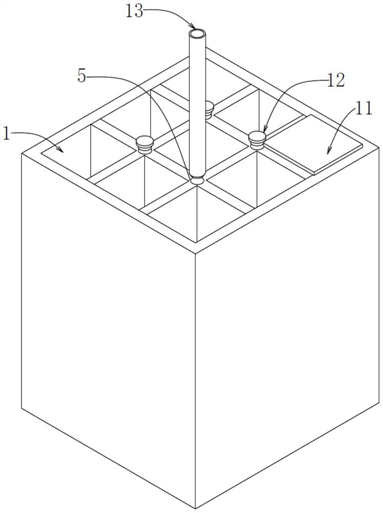
[0025] see Figure 1-5 , the present invention provides a technical solution:

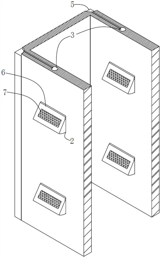
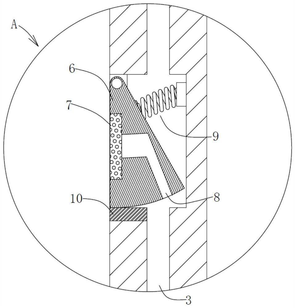
[0026] A sealed well-type landfill gas discharge structure, including several well-type landfill piles 1, the cross-section of the well-type landfill piles 1 is rectangular, and several well-type landfill piles 1 are arranged in an array, and each well-type landfill pile 1 The inner wall of the buried pile 1 is evenly spaced with a number of gas-liquid outlets 2 from top to bottom. The gas-liquid outlets 2 are connected through the separation channel 3 vertically arranged inside the side wall of the well-type landfill 1. The bottom of the separation channel 3 is connected to the seepage The filtrate collection tank 4 is connected, and the upper end of the separation channel 3 is connected with some total gas collection pipes 5 through pipelines;

[0027] The inside of the well-type landfill pile 1 is used for vertically layered landfilling of garbage, and the garbage sent into the inside of the we...


PUM


Abstract

The invention provides a sealed well-type garbage landfill gas emission structure comprising multiple well-type landfill piles, the cross section of each well-type landfill pile is rectangular, and multiple gas-liquid lead-out openings are evenly formed in the inner wall of each well-type landfill pile from top to bottom at intervals. The gas-liquid lead-out openings communicate through separation passageways vertically arranged in the side walls of the well type landfill piles, sealing fan-shaped plates are movably installed in the multiple gas-liquid lead-out openings through rotating shafts, and an extrusion spring is fixedly installed on the side, located on the corresponding separation passageway, of each sealing fan-shaped plate. Through the arrangement of the well type landfill piles, compared with an open type open air layered soil covering landfill mode, the overflow condition of waste gas is easier to control, garbage in different height areas in the same well type landfill pile can be subjected to fermentation waste and percolate recovery, the percolate and the waste gas can be more uniformly evacuated, centralized collection and treatment are facilitated, and the quality conditions of underground water and air around landfill sites are greatly improved.

Description

technical field [0001] The invention relates to the technical field of garbage landfill structures, in particular to a gas discharge structure of a sealed well type garbage dump landfill. Background technique [0002] The landfill is a place where garbage is piled up under the sanitary landfill method. The sanitary landfill is widely used in China because of its low cost and good sanitation. The leachate treatment and waste gas recovery issues in the construction of the landfill are The key to determining the success of landfill technology is directly related to the degree of pollution of landfill to groundwater and air environment. Therefore, how to solve the waste gas generated by leachate and anaerobic decomposition has become a problem that needs to be solved at present; [0003] In the prior art, the application number is "CN200710167987.6", a landfill that can use waterproof pads to prevent the leakage of landfill gas, including at least one layer of landfill, whose si...

Claims


Application Information

Patent Timeline
Patent Type & Authority Applications(China)
IPC IPC(8): B09B1/00E03F5/10
CPCB09B1/00E03F5/10Y02W30/30
Inventor 朱仁俊
Owner NANJING YUZHI INTELLIGENT TECH CO LTD
Why Eureka
Try Eureka