Light module for a lighting device of a motor vehicle

A technology for lighting devices and optical modules, which is applied to the parts of lighting devices, lighting devices, fixed lighting devices, etc., can solve the problems of brightness drop, uncompact solution, and failure to achieve luminous intensity, etc., and achieve the effect of small thermal resistance

Inactive Publication Date: 2012-01-11
AUTOMOTIVE LIGHTING REUTLINGEN GMBH
View PDF7 Cites 18 Cited by
  • Summary
  • Abstract
  • Description
  • Claims
  • Application Information

AI Technical Summary

Problems solved by technology

If a more suitable working point is selected, the brightness will decrease and the required luminous intensity cannot be achieved
To achieve high luminous intensities, multiple individual light modules can be used, which naturally leads to a less compact solution

Method used


Image

  • Light module for a lighting device of a motor vehicle
  • Light module for a lighting device of a motor vehicle
  • Light module for a lighting device of a motor vehicle

Examples


Embodiment Construction

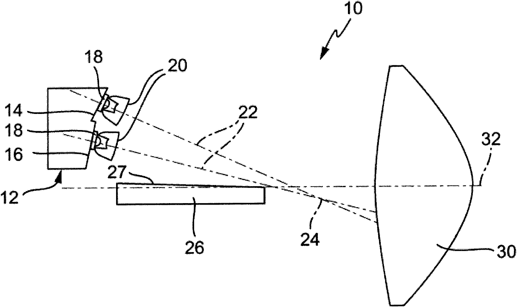
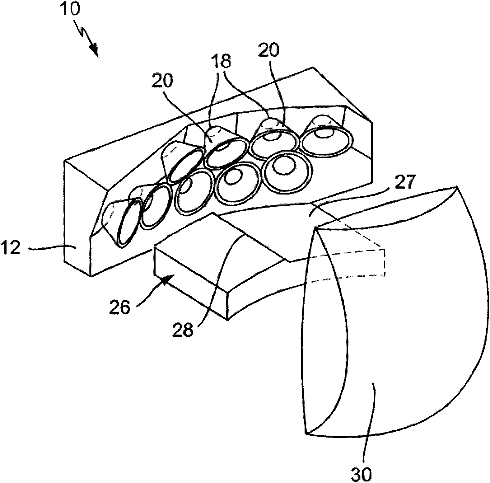
[0037] figure 1 Shows a side view in vertical section of a first embodiment of a light module 10 according to the invention for a lighting device for a motor vehicle, figure 2 A perspective view of the light module 10 is shown. The optical module 10 has a heat sink 12 made of a material with high thermal conductivity, such as aluminum or copper. A plurality of semiconductor light sources designed as light-emitting diodes 18 are arranged on two planes 14 and 16 formed separately from one another on the concavely curved side of the heat sink 12 . The first plane 14 has 4 LEDs 18 arranged next to each other, the second plane 16 has 5 LEDs 18 arranged next to each other, so that the LEDs 18 result in a compact unit. The light emitting diodes 18 of each of the planes 14 and 16 can be controlled in groups. The light-emitting diodes 18 can also be controlled individually in order to switch them on or off individually as required. The light emitting diodes 18 can be dimmed indivi...


PUM


Abstract

The invention relates to a light module (10) for a lighting device of a motor vehicle, comprising at least one semiconductor light source (18) for emitting the light, at least one main optical unit (20;20') for concentrating light from the light source, a light shielding plate (26) and a secondary optical unit (30), wherein the light shielding plate (26) is used for shielding one part of the light beam, the secondary optical unit is used for imaging a part of the light across the light shielding plate (26) and a part of the light reflected from the light shielding plate (26), therefore the desired light distribution is obtained on the runway before the motor vehicle. The light shielding plate (26) extends basically on a horizontal plane, the plane comprises an optical axle (32) of the secondary optical unit (30). The light module (10) comprises a plurality of semiconductor light sources (18) for distributing at least one main optical unit (20;20'), wherein the main optical unit is positioned and designed that: at least one optical axle (22) with the main optical unit (20;20') extends in at least one plane and the plane is crossed with the horizontal surface of the light shielding plate (26).

Description

technical field [0001] The invention relates to a light module for a lighting device of a motor vehicle, which light module has at least one semiconductor light source for emitting light, at least one primary optical unit for bundling the emitted light, a shutter and a secondary optical unit, Wherein the shading plate extends in a substantially horizontal plane including the optical axis of the optical module, the shading plate is used to block a part of the beamed light, and the secondary optical unit is used to make a part of the light passing through the shading plate and on the shading plate A portion of the reflected light is imaged so that the desired light distribution is produced on the road ahead of the motor vehicle. Furthermore, the invention relates to a lighting device for a motor vehicle having at least one such light module for generating a light distribution on a roadway in front of the motor vehicle. Background technique [0002] Various lighting devices fo...

Claims


Application Information

Patent Timeline
Patent Type & Authority Applications(China)
IPC IPC(8): F21S8/12F21V13/00F21V29/00F21V14/00F21Y101/02
CPCF21S48/328B60Q2400/30F21S48/1159F21S48/1747B60Q2400/20F21S48/1104F21S48/125F21S48/1154F21S48/321F21S41/147F21S41/153F21S41/19F21S41/285F21S41/322F21S41/43F21S41/635F21S41/663F21S45/47F21S45/49
Inventor 沃尔夫冈·霍夫尔德克里斯蒂安·巴克伯杰
Owner AUTOMOTIVE LIGHTING REUTLINGEN GMBH
Why Eureka
Try Eureka