
Rotary base capable of automatically returning to original point

A rotating base, automatic return technology, applied in the direction of clamps, workpiece clamping devices, shafts, etc., can solve problems such as breakage, bending, easy damage or deformation of the cover, and achieve the effect of preventing damage or accidents and prolonging life.

Inactive Publication Date: 2021-06-01
孙侦铢
View PDF8 Cites 0 Cited by
  • Summary
  • Abstract
  • Description
  • Claims
  • Application Information

AI Technical Summary

Problems solved by technology

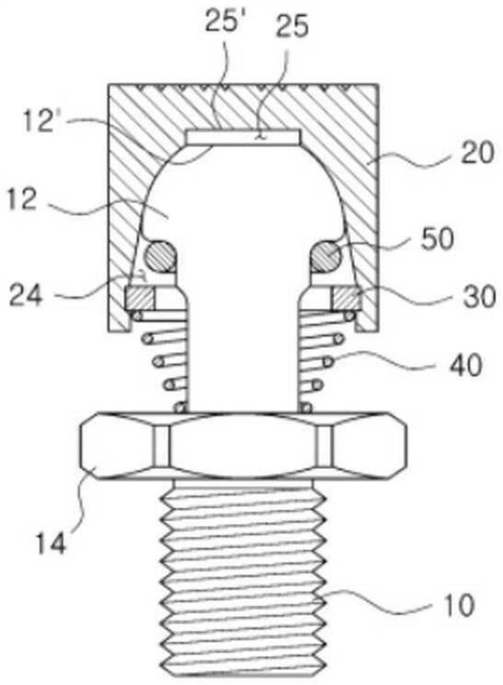
[0007] However, in the structure of the conventional rotating base, the cover is mounted on the ball and the cover directly compresses the mechanical product, so that the force compressing the cover is concentrated at the end of the ball, and the thin cover is prone to damage or deformation.
[0008] In addition, the cover can return to the original point by setting the compression spring formed on the lower side of the cover, but when the diameter of the lower end of the rotary support is smaller than that of the rotary support, and the inclined surface of the mechanical product is compressed, the The neck of the rotating support part is weakened, and there is a problem of bending or breaking
[0009] Moreover, currently on the market, the rotating base that can return to the origin is not used due to various problems, but the fact is that in the construction site, the rotating base that can fix or support mechanical products at various angles for cutting or moving operations can return to the origin The need for swivel bases has increased

Method used


Image

  • Rotary base capable of automatically returning to original point
  • Rotary base capable of automatically returning to original point
  • Rotary base capable of automatically returning to original point

Examples


Embodiment Construction

[0076] Hereinafter, an embodiment of the present invention will be described in more detail with reference to the drawings.

[0077] As a reference, the description with reference to the accompanying drawings is for easier understanding of the present invention, rather than limiting the scope of the present invention by them. In addition, when describing the present invention, when it is judged that the specific description of related known technologies is unnecessary and obscures the gist of the present invention, the specific description will be omitted.

[0078] figure 1 To show a section view of the swivel base showing the existing homing.

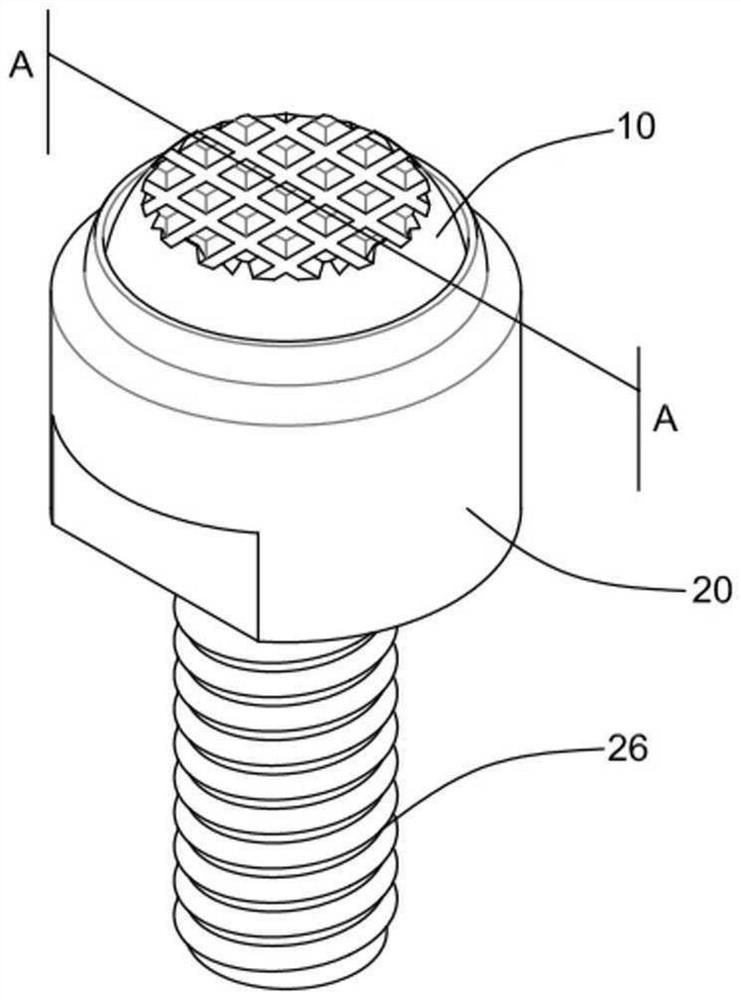
[0079] The invention relates to a rotating base used for fixing or moving mechanical products and being connected with one side of a fixture, and the upper surface of a compression ball is compressed with the surface of the mechanical products to fix the mechanical products.

[0080] Specifically, it relates to a case where the shape...


PUM


Abstract

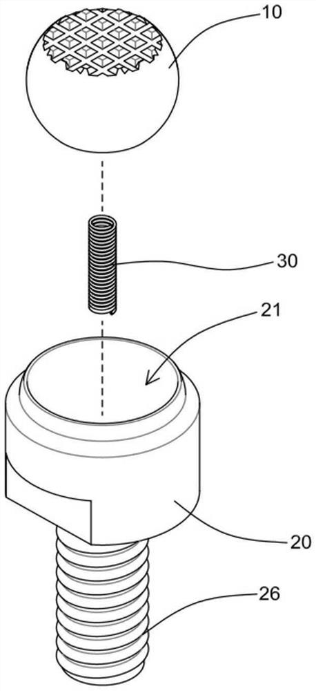
The invention provides a rotating base capable of automatically returning to an original point. The present invention relates to a rotary base, and more particularly, to a rotary base coupled to one side cross-section of a jig in order to fix or move a mechanical product, comprising: a compression ball in which an upper surface and a lower surface are flattened and a first elastic member insertion hole having a certain depth is formed in the center of the lower surface; a support member having an insertion groove formed on one side to accommodate the compression ball, a first return space formed on the lower side of the insertion groove, a second elastic member insertion hole formed at a certain depth in the center of the first return space, and a connection portion formed on the other side to be connectable to a jig; and an elastic member, one side end of which is inserted into each of the first elastic member insertion hole and the second elastic member insertion hole to elastically support the compression ball, and the upper surface of the compression ball compresses the mechanical product to be fixed or moved, and after the compression of the rotating compression ball is released, the compression ball returns horizontally.

Description

technical field [0001] The present invention relates to a rotating base capable of automatically returning to the origin, and more particularly to a rotating base capable of automatically returning to the origin, which can operate at different angles so as to effectively fix or support unevenness without deformation of mechanical products mechanical products. Background technique [0002] Usually, when the mechanical product is fixed and clamped, when the mechanical product enters the cutting process or performs mobile operations, various fixing fixtures need to be deformed according to the shape of the mechanical product and the working environment, and, according to the shape of the mechanical product and inclination require deformation of various applicable fixtures. [0003] The jig is a structure that is clamped on opposite pairs or one side. When the weight of the mechanical product is heavy, it is necessary to work in a state fixed by high-pressure compression. There...

Claims


Application Information

Patent Timeline
Patent Type & Authority Applications(China)
IPC IPC(8): B25B11/00
CPCB25B11/00B25B5/163F16C11/12F16C11/0685F16C2322/39F16C11/0695
Inventor 孙侦铢
Owner 孙侦铢
Learn More