Workpiece machining method
A processing method and workpiece technology, applied in the field of workpiece processing, can solve the problem of low positioning accuracy and achieve the effect of improving positioning accuracy
- Summary
- Abstract
- Description
- Claims
- Application Information
AI Technical Summary
Problems solved by technology
Method used
Image

Examples
Embodiment 1
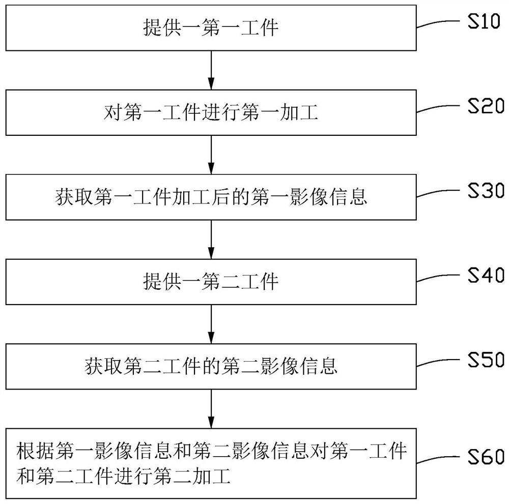
[0104] figure 1 For a flow chart of a workpiece processing method provided in an embodiment of the present application, please refer to figure 1 , a workpiece processing method, comprising the steps of:
[0105] S10: providing a first workpiece;
[0106] S20: performing first processing on the first workpiece;
[0107] S30: Acquiring the first image information after the processing of the first workpiece;
[0108] S40: providing a second workpiece;
[0109] S50: Acquire second image information of the second workpiece;
[0110] S60: Perform second processing on the first workpiece and the second workpiece according to the first image information and the second image information.
[0111] It should be noted that the above workpiece processing method is mainly used in the precise assembly between two workpieces. Among them, the first image information after processing of the first workpiece and the second image information of the second workpiece are obtained, and operatio...
Embodiment 2
[0132] The workpiece processing method provided in the present application can be applied to dispensing, assembling and bonding of the frame 200 and the glass 300 in consumer electronics products. In one embodiment, the first workpiece is the frame 200 , and the second workpiece is the glass 300 . The assembly process of frame 200 and glass 300 is as follows:
[0133] Firstly, the frame 200 is scanned by the first image acquisition system to obtain the third image information and the first setting parameters of the frame 200, and glue is dispensed on the designated part of the frame 200 according to the third image information and the first setting parameters. The glass 300 is scanned by the second image acquisition system to obtain the fourth image information and the second setting parameters of the glass 300, and according to the fourth image information and the second setting parameters, glue is dispensed on the designated part of the glass 300 and turned over after dispen...
Embodiment 3
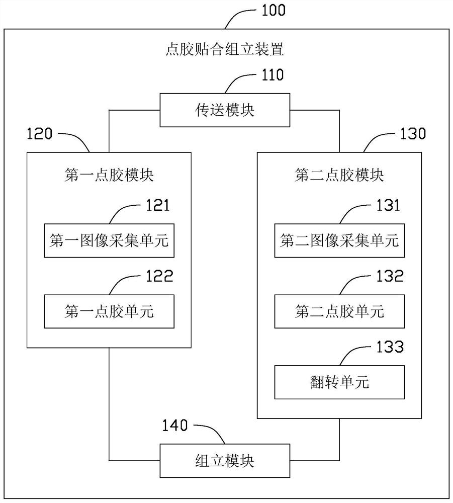
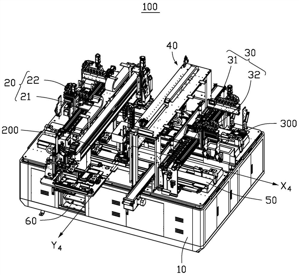
[0143] image 3 For the three-dimensional schematic diagram of the dispensing and bonding assembly device 100 in the third embodiment of the present application, please refer to image 3 , a dispensing and laminating assembly device 100 for assembling glass 300 and frame 200, including workbench 10, frame dispensing area 20, glass dispensing area 30, assembly area 40, transfer unit 50 and feeding area 60. The frame dispensing area 20 is located at one end of the workbench 10, and is used to collect the image information of the frame 200 and dispense glue on the frame 200; the glass dispensing area 30 is located at the other end of the workbench 10, and is used to collect the image information of the glass 300 and Dispensing of glass 300; assembly area 40, set between frame dispensing area 20 and glass 300 dispenser, for assembling frame 200 and glass 300 after dispensing; transfer unit 50, set on workbench 10 , for transporting the frame 200 and the glass 300 to the frame di...
PUM
 Abstract
Description
Claims
Application Information
 - R&D
- Intellectual Property
- Life Sciences
- Materials
- Tech Scout
- Unparalleled Data Quality
- Higher Quality Content
- 60% Fewer Hallucinations
Browse by: Latest US Patents, China's latest patents, Technical Efficacy Thesaurus, Application Domain, Technology Topic, Popular Technical Reports.
© 2025 PatSnap. All rights reserved.Legal|Privacy policy|Modern Slavery Act Transparency Statement|Sitemap|About US| Contact US: help@patsnap.com