Energy-saving paper box drying equipment

A technology of drying equipment and carton, applied in drying, drying machine, lighting and heating equipment, etc., can solve the problems of insufficient contact of viscose glue, slow solidification speed of viscose glue, etc., to increase the spraying force , the effect of accelerating the solidification speed and increasing the spraying force

Inactive Publication Date: 2021-06-01
张顺妹
View PDF0 Cites 0 Cited by
  • Summary
  • Abstract
  • Description
  • Claims
  • Application Information

AI Technical Summary

Problems solved by technology

[0003] Based on the discovery by the inventors above, the existing energy-saving carton drying equipment mainly has the following disadvantages, for example: when the carton is dried, because the sticky glue is placed in the interlayer of the carton, The airflow in the dryer is mainly concentrated on the end face of the carton, so that the viscose placed in the interlayer of the carton is not in sufficient contact with the airflow, resulting in a slower solidification of the viscose in the carton

Method used


Image

  • Energy-saving paper box drying equipment
  • Energy-saving paper box drying equipment
  • Energy-saving paper box drying equipment

Examples


Embodiment 1

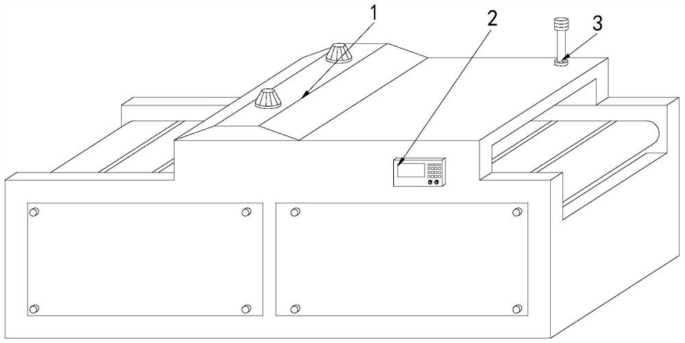
[0026] Example 1: Please refer to Figure 1-Figure 6 , the specific embodiments of the present invention are as follows:

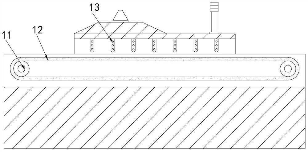
[0027] Its structure includes a main body 1, a control panel 2, and a warning light 3. The front end of the main body 1 is provided with a control panel 2, and the warning light 3 is embedded in the middle of the top of the main body 1. The main body 1 includes a rotating shaft 11, Conveyor belt 12, drying device 13, said rotating shaft 11 is provided with two, and is arranged on the inner two ends of main body 1 respectively, and described conveying belt 12 is nested between two rotating shafts 11, and described drying device 13 Installed on the upper end of the conveyor belt 12.

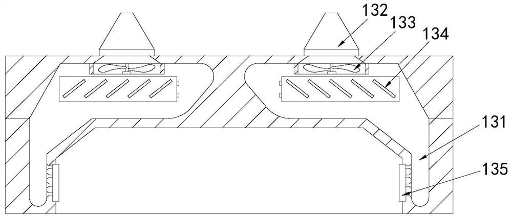
[0028] The drying device 13 includes a ventilation groove 131, an air inlet 132, a rotary fan 133, a heat conducting sheet 134, and a side drying device 135. The ventilation groove 131 is provided with two, and is respectively arranged at both ends of the air inlet 132, The a...

Embodiment 2

[0033] Example 2: Please refer to Figure 7-Figure 8 , the specific embodiments of the present invention are as follows:

[0034] The air spray head a43 includes a flow tank c1, an air inlet c2, a concentration block c3, and an air injection port c4. The flow tank c1 is arranged in the middle of the inside of the air spray head a43, and the air inlet c2 is installed at the center of the flow tank c1. At the front end, there are eight concentrating blocks c3 arranged horizontally on the upper and lower end faces of the flow tank c1 in groups of four, the air injection port c4 is located at the end of the flow tank c1, and the end face of the concentrating block c3 The end is bent toward the middle, which is beneficial to guide the airflow to the middle of the flow cell c1.

[0035]The air jet c4 includes a movable groove c41, a return spring c42, and an air storage block c43. There are two movable grooves c41 located at the upper and lower ends of the air jet c4 respectively. ...


PUM


Abstract

The invention discloses energy-saving paper box drying equipment. The energy-saving paper box drying equipment structurally comprises a main body, a control panel and an alarm lamp, the control panel is arranged at the front end of the main body, the alarm lamp is fixedly embedded in the middle of the top of the main body, the main body comprises a rotating shaft, a conveying belt and a drying device, and the drying device comprises a ventilation groove, an air inlet, a rotating fan, a heat conduction piece and a side drying device; and the side drying device comprises an air storage tank, an air inlet, a corrugated sheet and an air outlet head, the air outlet head comprises an air outlet groove, a guide plate and an air spraying head, and the guide plate comprises a fixed block, an air guide groove and an air collecting block. According to the drying equipment, the position of the corrugated sheet in the side drying device is arranged to be aligned with the air outlet head, so that air flow can flow on the end face of the corrugated sheet back and forth, the jet force of the air flow is increased, the air flow can be transversely blown out from the side drying device, the air flow can enter gaps in a paper box to be in contact with an adhesive, and the adhesive can be rapidly solidified.

Description

technical field [0001] The invention relates to the field of drying equipment for cartons, in particular to an energy-saving drying equipment for cartons. Background technique [0002] In the process of carton processing, it is necessary to glue the carton with glue to close the port of the carton, and when the glue is applied to the end of the carton, it takes a certain amount of time to solidify , so that the carton needs to be dried by a dryer to speed up the solidification speed of the glue in the carton, so that the carton can be processed in the next process. [0003] Based on the discovery by the inventors above, the existing drying equipment for energy-saving cartons mainly has the following disadvantages, for example: when drying the cartons, because the adhesive is placed in the interlayer of the carton The airflow in the dryer is mainly concentrated on the end face of the carton, so that the viscose placed in the interlayer of the carton is not in sufficient cont...

Claims


Application Information

Patent Timeline
IPC IPC(8): F26B9/06F26B21/00B05D3/04
CPCB05D3/0413F26B9/06F26B21/004
Inventor 张顺妹
Owner 张顺妹
Why Eureka
Try Eureka