
Cleaning device for electric blanket

A cleaning device and a technology for electric blankets, which are applied to the configuration of equipment for processing textile materials, removing liquid/gas/vapor by suction, and treating textile materials by spraying/jetting, etc. , troublesome operation, etc.

Inactive Publication Date: 2018-05-18
宁波隆锐机械制造有限公司
View PDF1 Cites 0 Cited by
  • Summary
  • Abstract
  • Description
  • Claims
  • Application Information

AI Technical Summary

Problems solved by technology

[0002] Electric blankets are a common heating appliance. The materials that make up the interlayer pads of existing electric blankets are usually felt-like materials. The two interlayers are usually bonded or thermocompressed to form multiple strips for wearing electric heating pads. The channel of the wire, the existing electric blanket has the following disadvantages: when the bonding or thermocompression contact meets water and is stressed, the bonding part will be disengaged, so the existing electric blanket cannot be directly cleaned. If it needs to be cleaned, It is necessary to add a detachable coat for cleaning, which is troublesome to operate
[0004] The electric blanket in the above-mentioned patent document adopts pure cotton cloth and sewing to form a channel for passing through the heating wire, and cleans through the sewing channel. However, it needs to be dried after cleaning. During the drying process, cleaning There is still water in the part, and the water will flow into the position of the heating wire along the gap, which will affect the use of the electric blanket

Method used


Image

  • Cleaning device for electric blanket

Examples


Embodiment Construction

[0022] Further detailed explanation through specific implementation mode below:

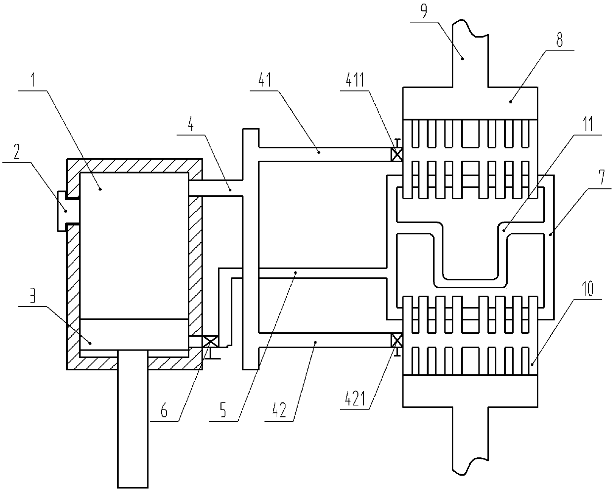
[0023] The reference signs in the accompanying drawings of the description include: inflatable box 1, cork 2, piston rod 3, first air delivery pipe 4, first branch pipe 41, second branch pipe 42, first valve 411, second valve 421, The second air pipe 5, the third valve 6, the pressure pipe 7, the storage chamber 8, the water pipe 9, the injection pipe 10, and the U-shaped pipe 11.

[0024] The embodiment is basically as attached figure 1 Shown: a cleaning device for electric blankets, including pressure tube 7 and U-shaped tube 11, pressure tube 7 is a rectangular frame, the upper part of pressure tube 7 and U-shaped tube 11 is made of steel material, pressure tube 7 and U-shaped tube 11 The lower part is made of plastic material, the U-shaped tube 11 is arranged in the pressure tube 7, and the two ends of the U-shaped tube 11 communicate with the pressure tube 7, and the left side of the pressu...


PUM


Abstract

The invention discloses a cleaning device for an electric blanket. The device comprises an aerating box which is internally provided with a piston rod capable of moving in a reciprocating mode, a first air delivery pipe is arranged on the upper portion of the aerating box, a second air delivery pipe is arranged on the lower portion of the aerating box, a third valve is arranged in the second air delivery pipe, a first branched pipe and a second branched pipe which are communicated with the first air delivery pipe are arranged on the first air delivery pipe, the first branched pipe is internally provided with a first valve, the second branched pipe is internally provided with a second valve, a rectangular frame pressure pipe is arranged one side of the aerating box, a U-type pipe communicated with the pressure pipe is arranged on the pressure pipe, the pressure pipe is communicated with the second air delivery pipe, multiple injection pipes facing the U-type pipe are arranged on the pressure pipe, the injection pipes are uniformly distributed at the upper end and the lower end of the pressure pipe, the injection pipes located at the upper end of the pressure pipe are communicated with the first branched pipe, and the injection pipes located at the lower end of the pressure pipe are communicated with the second branched pipe. Both cleaning and rapid drying can be achieved.

Description

technical field [0001] This field belongs to the technical field of household appliances, and in particular relates to a cleaning device for electric blankets. Background technique [0002] Electric blankets are a common heating appliance. The materials that make up the interlayer pads of existing electric blankets are usually felt-like materials. The two interlayers are usually bonded or thermocompressed to form multiple strips for wearing electric heating pads. The channel of the wire, the existing electric blanket has the following disadvantages: when the bonding or thermocompression contact meets water and is stressed, the bonding part will be disengaged, so the existing electric blanket cannot be directly cleaned. If it needs to be cleaned, It is necessary to add a detachable coat to clean it, which is cumbersome to operate. [0003] In order to solve the above technical problems, a Chinese patent (application number CN200520067806.9) discloses a washable electric blan...

Claims


Application Information

Patent Timeline
Patent Type & Authority Applications(China)
IPC IPC(8): D06B1/02D06B15/04D06B23/20
CPCD06B1/02D06B15/04D06B23/20
Inventor 王健
Owner 宁波隆锐机械制造有限公司
Learn More