
Intelligent appearance detection machine for optical module connector die casting and method thereof

A technology for optical module connectors and die-casting parts, which is applied in the field of detection of optical module connector die-casting parts, can solve problems such as waste, affect the production process, and cannot meet production needs, and achieve the effect of high detection accuracy

Inactive Publication Date: 2021-06-01
DONGGUAN XINGHE PRECISION DIECASTING MOLD CO LTD
View PDF7 Cites 5 Cited by
  • Summary
  • Abstract
  • Description
  • Claims
  • Application Information

AI Technical Summary

Problems solved by technology

[0002] The optical module connector is composed of a casing, optoelectronic devices, functional circuits and optical interfaces, among which the casing is mainly made of die-casting technology. During the production and manufacturing process of die-casting hardware structural parts, the optical module connector die-casting parts are used in various processes. There is a chance that there will be defects in the appearance. If these defective optical module connector die-casting parts are assembled into the optical module, the quality of the optical module will be unqualified, causing waste and affecting the production process. Therefore, the die-casting of the optical module connector It is very necessary to carry out visual inspection of parts. The existing traditional method for visual inspection of optical module connector die-casting parts is that the operator takes the product and identifies the qualified product and the unqualified product through human eyes. The defect of this traditional method The reason is that the efficiency of manual pick-and-place inspection is low, and after a long time, manual inspection will inevitably lead to misjudgments and missed inspections due to visual fatigue, so that unqualified products cannot be found in time, and the detection reliability is poor, which cannot meet production needs

Method used


Image

  • Intelligent appearance detection machine for optical module connector die casting and method thereof
  • Intelligent appearance detection machine for optical module connector die casting and method thereof
  • Intelligent appearance detection machine for optical module connector die casting and method thereof

Examples


Embodiment Construction

[0025]The specific embodiments of the present invention will be further described below with reference to the accompanying drawings:

[0026]In the description of the invention, it is to be described in the terms "center", "upper", "lower", "left", "right", "vertical", "horizontal", "within", "outside", etc. The orientation or positional relationship indicated is based on the orientation or positional relationship shown in the drawings, is merely description, rather than indicating or implying that the location or component must have a particular orientation. Construct and operation, so it is not understood to be the limitation of the invention.

[0027]In the description of the present invention, it is to be described in that, unless otherwise expressly specified and defined, the term "mount", "connected", "connection" should be broadly understood, for example, may be fixed connection, or detachable Connect, or integrate; it can be mechanical connection, or electrical connection; may be ...


PUM


Abstract

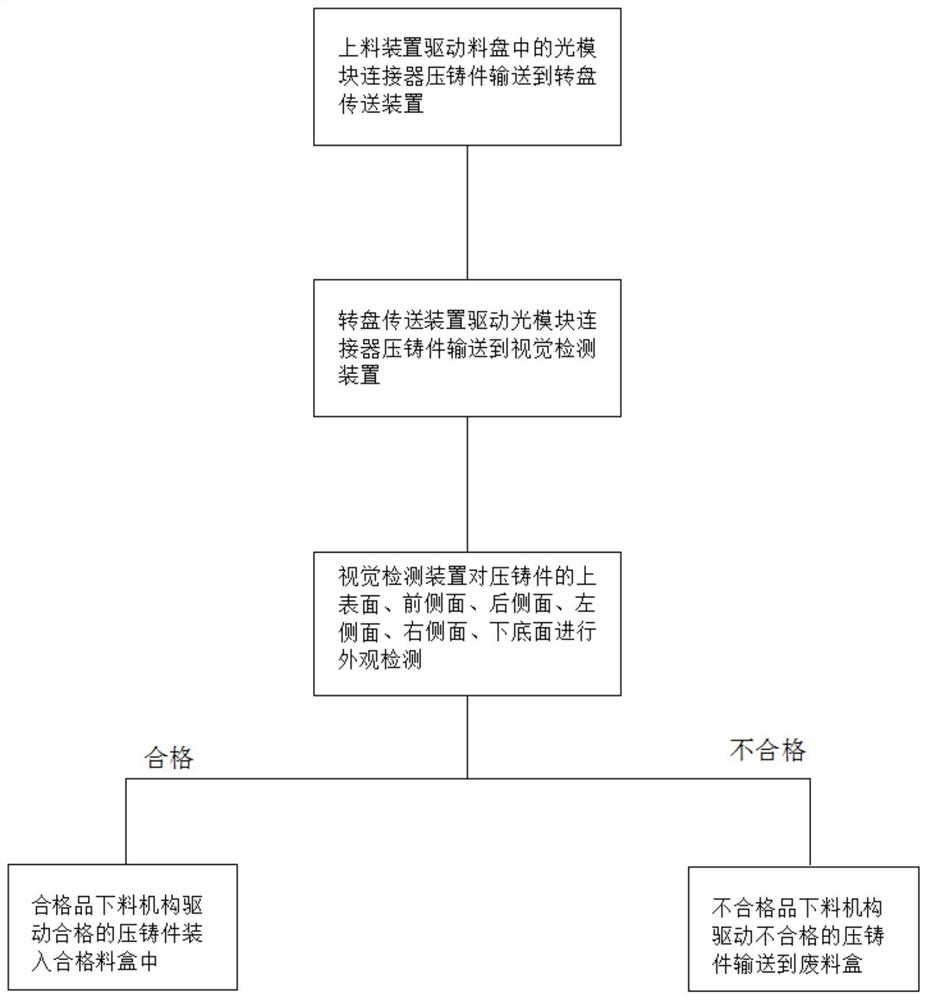
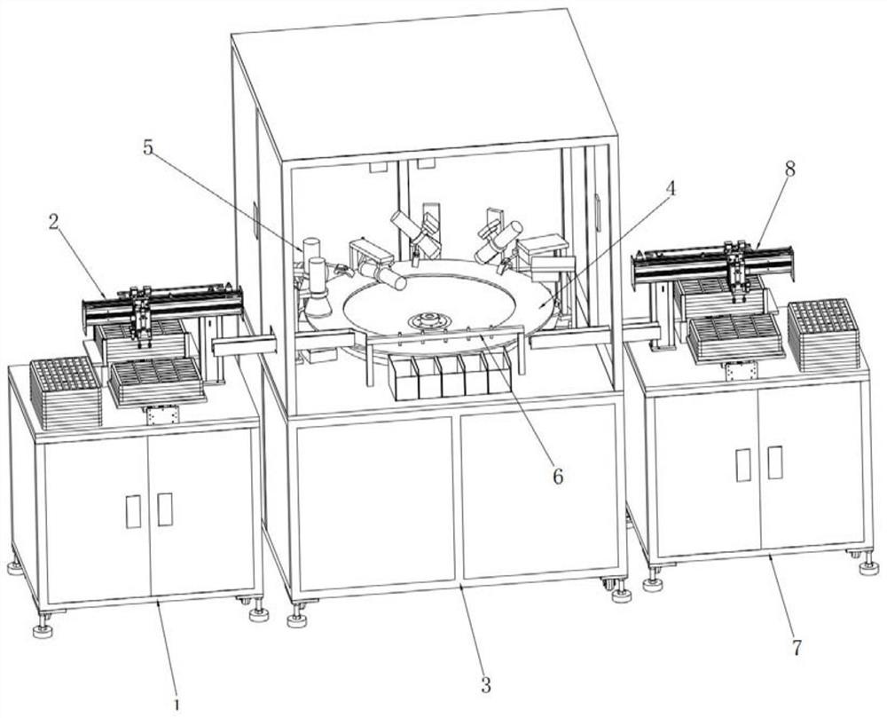
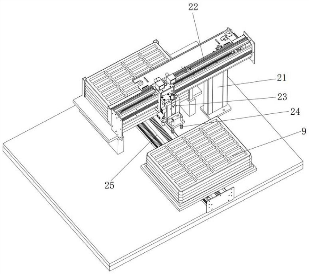
The invention relates to an intelligent appearance detection machine for an optical module connector die casting and a method thereof. The intelligent appearance detection machine comprises a feeding machine frame, a feeding device, a main machine frame, a rotary disc conveying device, a visual detection device, an unqualified product discharging device, a discharging machine frame and a qualified product discharging device, the feeding machine frame is located on one side of the main machine frame, and the discharging machine frame is located on the other side of the main machine frame; the feeding device drives the optical module connector die castings in the trays to be conveyed to the rotary disc conveying device, the rotary disc conveying device drives the optical module connector die castings to be conveyed to the visual detection device, and the visual detection device detects whether the appearances of the die castings are qualified or not. The intelligent appearance detection machine for the optical module connector die casting and the method thereof have the advantages that the optical module connector die casting does not need to be manually taken, placed, observed and detected, the whole process is automatic, the efficiency is high, the labor cost is saved, the detection precision is high, and the modern production requirement is met.

Description

Technical field[0001]The present invention relates to the field of optical module connector die-casting detection, and more particularly to an appearance intelligent machine for optical module connector die castings and a detection method thereof.Background technique[0002]The optical module connector is composed of a casing, an optoelectronic device, a functional circuit, and an optical interface, and the cabin mainly made of die-casting processes, during the production process, each step works time module connector die casting The organic rate will produce a defective defect in appearance. If these defective optical module connector die castings are assembled into the optical module, the quality of the optical module is unqualified, resulting in a waste affecting the production process, so the optical module connector is cast The appearance test is very necessary. The traditional method of existing detection of the optical module connector is detected is that the operation worker t...

Claims


Application Information

Patent Timeline
Patent Type & Authority Applications(China)
IPC IPC(8): G01N21/89B07C5/02B07C5/34B07C5/38
CPCG01N21/89B07C5/02B07C5/34B07C5/38
Inventor 唐征平肖大鹏
Owner DONGGUAN XINGHE PRECISION DIECASTING MOLD CO LTD
Learn More