A transducer drive system and method

A driving method and technology of a driving system, applied in the direction of output power conversion device, conversion of AC power input to DC power output, electrical components, etc., which can solve problems such as large amount of calculation, difficulty in realizing automation, high requirements for excitation circuit and sampling circuit, etc. , to achieve the effect of impedance matching and fully automatic driving

Active Publication Date: 2022-03-11
SHANGHAI UNIV
View PDF7 Cites 0 Cited by
  • Summary
  • Abstract
  • Description
  • Claims
  • Application Information

AI Technical Summary

Problems solved by technology

This method is relatively complicated, and has relatively high requirements for the excitation circuit and sampling circuit, and at the same time, the calculation amount is large, and it is difficult to realize automation.

Method used


Image

  • A transducer drive system and method
  • A transducer drive system and method
  • A transducer drive system and method

Examples


Embodiment Construction

[0056] The following will clearly and completely describe the technical solutions in the embodiments of the present invention with reference to the accompanying drawings in the embodiments of the present invention. Obviously, the described embodiments are only some, not all, embodiments of the present invention. Based on the embodiments of the present invention, all other embodiments obtained by persons of ordinary skill in the art without making creative efforts belong to the protection scope of the present invention.

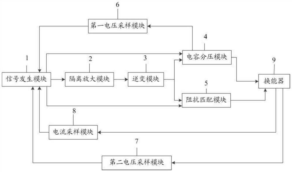
[0057] The transducer drive system of the present invention drives the transducer to work, isolates the signal generation module and the inverter module through the isolation and amplification module, and amplifies the first pulse signal generated by the signal generation module; the amplified first pulse signal of the inverter module Driven by the signal, the DC voltage is inverted to obtain the second pulse signal, and sent to the impedance matching module an...


PUM


Abstract

The invention discloses a transducer drive system for driving the transducer to work; the transducer drive system includes a signal generation module, an isolation amplification module, an inverter module, an impedance matching module, a capacitor voltage divider module, a first The voltage sampling module, the second voltage sampling module and the current sampling module; the signal generation module outputs the first pulse signal to obtain the second pulse signal through the isolation amplification module and the inverter module, and the signal generation module outputs the first control signal to control the impedance matching module to switch The transducer performs impedance matching, the signal generation module outputs the second control signal to control the capacitor voltage divider module, and under the drive of the second pulse signal, changes the voltage at both ends of the transducer; according to the first voltage sampling module, the second sampling module And the sampling signal of the current sampling module, and finally realize the automatic impedance matching of the transducer, and then realize the fully automatic driving of the transducer.

Description

technical field [0001] The invention relates to the field of piezoelectric transducer drive control, in particular to a transducer drive system and method. Background technique [0002] The generation of ultrasonic waves requires a transducer to work, converting electrical energy into mechanical energy. Ultrasonic transducers need to provide a voltage with a calibrated frequency when they are manufactured to work. At the same time, during the working process of the transducer, due to the influence of various factors, its impedance properties will change, and its resonance frequency will also drift. Therefore, the work of the transducer requires the precise cooperation of the drive power supply of the transducer in order to work smoothly. [0003] The ultrasonic transducer is made of metal-plated materials on the surface of piezoelectric ceramics, and its equivalent circuit model is as follows: figure 1 As shown, the electrical impedance is generally a complex impedance. T...

Claims


Application Information

Patent Timeline
Patent Type & Authority Patents(China)
IPC IPC(8): H02M7/5395H02M7/5387
CPCH02M7/5395H02M7/53871
Inventor 李喜峰张选峰安纯尧苏含玉
Owner SHANGHAI UNIV
Why Eureka
Try Eureka