Energy-saving irrigation device for hydraulic engineering

A technology for water conservancy projects and irrigation devices, which is applied in watering devices, fertilizing devices, and devices for capturing or killing insects, etc., can solve problems such as increased cost, large flow, and inability to spray pesticides or fertilizers, so as to improve the utilization rate. Effect

Inactive Publication Date: 2021-06-04
朱金平
View PDF0 Cites 0 Cited by
  • Summary
  • Abstract
  • Description
  • Claims
  • Application Information

AI Technical Summary

Problems solved by technology

[0003] When irrigating farmland, common irrigation equipment uses one pipe to dredge multiple atomizing nozzles for spraying, and the spraying flow rate of the atomizing nozzles that are closer to the direction of pipe diversion is compared with that of fog farther away from the direction of pipe diversion. The flow rate of chemical nozzle is too large, which leads to uneven irrigation and spraying. Moreover, plants need to spray pesticides or fertilizers more or less during the growth process, but at this stage, irrigation equipment cannot realize pesticides or fertilizers.
[0004] In some relatively arid desert areas, when irrigating, the water pipes are generally pulled into the crops to irrigate the crops on a large scale. In other words, some places are relatively dry and lack water, while some places are relatively humid. If the same large-scale irrigation is performed, on the one hand, it will cause uneven irrigation and waste water resources. It is difficult to perform reasonable energy-saving irrigation during irrigation. On the one hand, when the land to be irrigated is far away from the water source, it is necessary to pull a long water pipe, so that the corresponding cost will also increase. Therefore, it is urgent to design an energy-saving irrigation device for water conservancy projects to solve the shortcomings of the existing technology

Method used


Image

  • Energy-saving irrigation device for hydraulic engineering
  • Energy-saving irrigation device for hydraulic engineering
  • Energy-saving irrigation device for hydraulic engineering

Examples


Embodiment 1

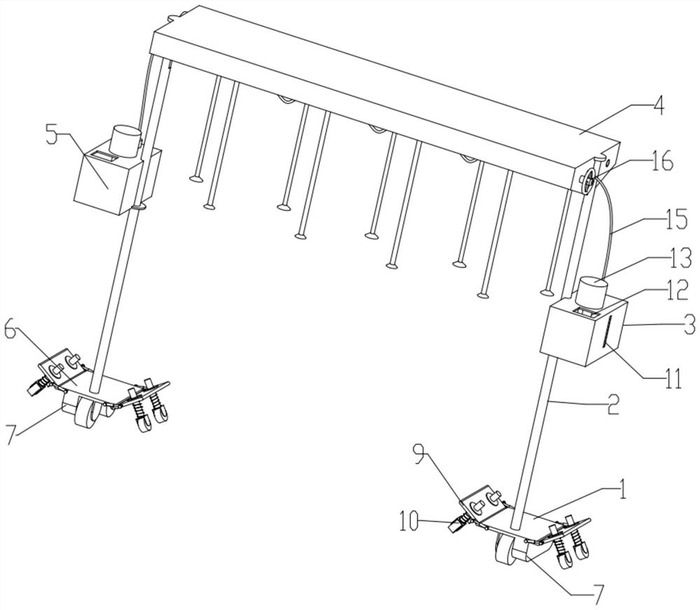
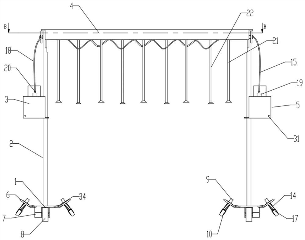
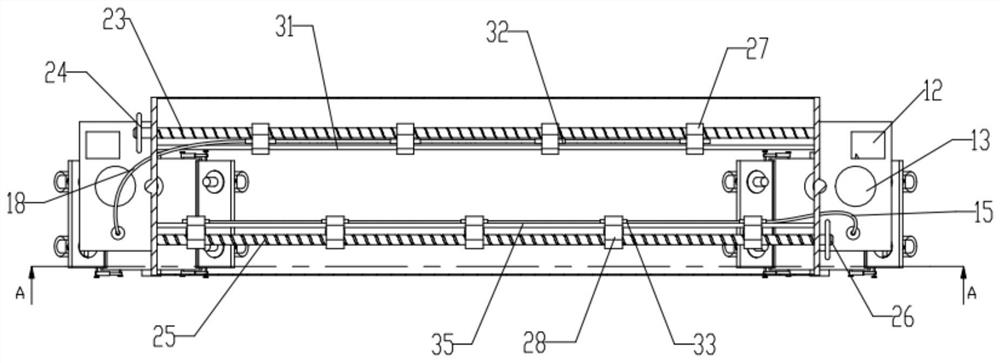
[0033] An energy-saving irrigation device for water conservancy projects, comprising a mobile base 1, a first water outlet tank 3, a second water tank 5, and a workbench 4. The upper part of the mobile base 1 is provided with a support rod 2, and the bottom of the support rod 2 is in contact with the mobile The base 1 is fixed, and the top of the support rod 2 is fixed to the workbench 4. The inside of the workbench 4 is provided with a first screw screw 23 and a second screw screw 25, the first screw screw 23 and the second screw screw Bar 25 is all rotatably connected with the side wall of workbench 4 by bearing, and the circumferential direction of the first screw screw 23 is provided with the first slide block 27, and the first screw screw 23 runs through the first slide block 27, and the first slide block 27 Internally provided with an internal thread that cooperates with the external thread of the first screw screw 23, the circumferential direction of the second screw scr...

Embodiment 2

[0035] The outer sides of the first water outlet tank 3 and the second water tank 5 are equipped with a liquid level gauge 11, the liquid level gauge 11 is made of transparent glass, and the first water outlet tank 3 and the second water outlet tank 3 can be detected by the liquid level gauge 11. The liquid storage situation of the two water tanks 5, in addition, when spraying pesticides or carrying out foliar fertilization, the liquid level gauge 11 can be used to proportion a certain amount of pesticides or fertilizers, the first water outlet tank 3 and the second water tank The casing upper side of 5 is provided with water inlet 12, and stirring motor 13, and the power output end of stirring motor 13 is provided with stirring blade, and stirring blade stretches into the bottom of the first water outlet tank 3 and the second water tank 5, so The top of the first water outlet box 3 is provided with a first water outlet pipe 15, the first water outlet pipe 15 runs through the s...

Embodiment 3

[0037] The first sliders 27 are arranged at equal intervals along the axis direction of the first screw screw 23, and the second sliders 28 are arranged at equal intervals along the axis direction of the second screw screw 25. A slide block 27 is located between the two second slide blocks 28, the first slide block 27 is provided with a first guide rod 31 on the side away from the first screw screw 23, and the two ends of the first guide rod 31 are fixed on On the inner wall of the workbench 4, the first guide rod 31 runs through the first slide block 27, the first slide block 27 is provided with a first three-way valve 32, and the second slide block 28 is far away from the second screw screw 25. One side is provided with second guide rod 35, and the two ends of second guide rod 35 are fixed on the inner wall of workbench 4, and second guide rod 35 runs through first slide block 27, and first slide block 27 is provided with second three. Through the valve 33, the left side of ...


PUM


Abstract

The invention relates to the technical field of hydraulic engineering, in particular to an energy-saving irrigation device for hydraulic engineering. The energy-saving irrigation device is mainly used for water-saving irrigation of hydraulic engineering and comprises a movable base, a first water outlet tank, a second water outlet tank and a workbench. A supporting rod is arranged on the upper part of the movable base, a first spiral lead screw and a second spiral lead screw are arranged in the workbench, and the first spiral lead screw and the second spiral lead screw are rotationally connected with the side wall of the workbench through bearings; a first sliding block is arranged in the circumferential direction of the first spiral lead screw, and a second sliding block is arranged in the circumferential direction of the second spiral lead screw; and spraying pipes are arranged under the first sliding block and the second sliding block, auxiliary supporting plates are symmetrically arranged on the left side and the right side of the movable base, and driving structures are arranged at the bottoms of the auxiliary supporting plates. The energy-saving irrigation device for the hydraulic engineering can spray water for irrigation, and can spray pesticide or fertilizer to crops in the plant growth process.

Description

technical field [0001] The invention relates to the technical field of water conservancy engineering, and is mainly used for water-saving irrigation of hydraulic engineering, in particular to an energy-saving irrigation device for water conservancy engineering. Background technique [0002] Water conservancy projects are projects built to control and allocate natural surface water and groundwater to achieve the purpose of eliminating harm and rejuvenating profits. Also known as water engineering. Water is an indispensable precious resource for human production and life, but its natural state does not fully meet human needs. Only by building water conservancy projects can we control water flow, prevent floods, and regulate and distribute water to meet the needs of people's life and production for water resources. [0003] When irrigating farmland, common irrigation equipment uses one pipe to dredge multiple atomizing nozzles for spraying, and the spraying flow rate of the a...

Claims


Application Information

Patent Timeline
Patent Type & Authority Applications(China)
IPC IPC(8): A01G25/09A01G25/16A01C23/04A01M7/00
CPCA01C23/042A01G25/09A01G25/16A01M7/0042Y02A40/22
Inventor 朱金平赵建龙孙耀科
Owner 朱金平
Why Eureka
Try Eureka