Bird repelling equipment for power grid equipment

A power grid equipment and bird repelling technology, applied in the power grid field, can solve the problems of increasing impeller friction, active dust adhesion, etc.

Inactive Publication Date: 2021-06-04
李翠莲
View PDF0 Cites 0 Cited by
  • Summary
  • Abstract
  • Description
  • Claims
  • Application Information

AI Technical Summary

Problems solved by technology

[0003] Based on the inventors’ findings above, the existing ones mainly have the following disadvantages. For example, when used in a windy and sandy environment, since the bird repelling equipment is installed on the top of the power grid equipment, and the connecting ends of the blades are designed with bearings, the bearings There is a groove gap between the type connecting end and the fixed rod for the ball to move, so that when the wind flows, it is easy to actively attach part of the sand and dust to the connecting end, and it is bonded with the oil in the bearing to increase the impeller's rotation. The friction force generated by the middle end surface

Method used


Image

  • Bird repelling equipment for power grid equipment
  • Bird repelling equipment for power grid equipment
  • Bird repelling equipment for power grid equipment

Examples


Embodiment 1

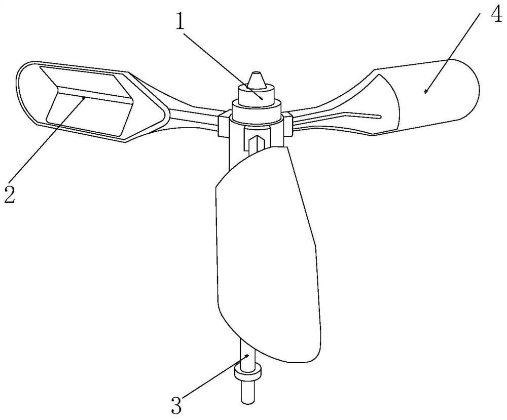
[0025] as attached figure 1 to attach Figure 5 Shown:

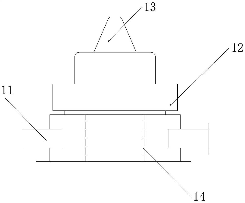
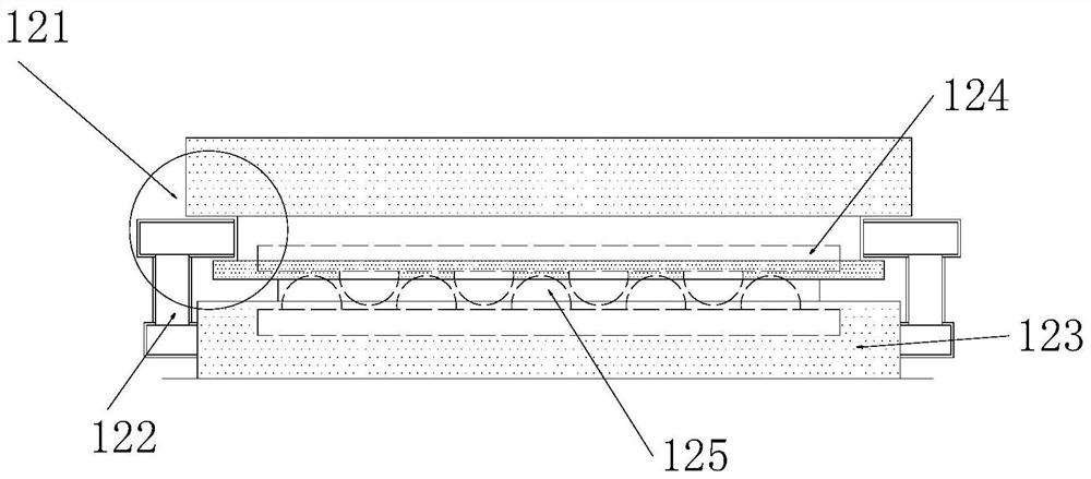
[0026] The invention provides a bird repelling device for power grid equipment, the structure of which includes an inlay shaft 1, a reflector 2, a connecting rod 3, and a blade 4, the inlay shaft 1 is inlaid directly above the connecting rod 3, and the reflector 2. Embedded on the inner end surface of the blade 4, the connecting rod 3 is embedded and installed directly below the blade 4, and the blade 4 is evenly arranged on the outer surface of the lower end of the embedded shaft 1; the embedded shaft 1 includes an embedded Strip 11, masking mechanism 12, pointed cone block 13, inlaying groove 14, the embedding solid bar 11 is embedded and installed on the outer end surface of the inlaying groove 14, and the covering mechanism 12 is nested and engaged on the inner upper end surface of the inlaying groove 14 The pointed cone block 13 is inlaid directly above the masking mechanism 12 , and the inlay groove 14 is located...

Embodiment 2

[0033] as attached Image 6 to attach Figure 7 Shown:

[0034]Wherein, the vibration mechanism 123 includes a rotating rod 231, an impact mechanism 232, a bevel block 233, and a third inlay groove 234. The rotating rod 231 is fixedly installed directly above the third inlay groove 234, and the impact mechanism 232 is evenly Set on the outer upper end surface of the third embedding groove 234, the inclined plane block 233 is embedded on the inner upper end surface of the vibration mechanism 123, the third embedding groove 234 is located directly below the inclined plane block 233, and the right side of the inclined plane block 233 The side end surface is inclined, and the impact mechanism 232 can be pushed to bend to the left by the counterclockwise rotation of the vibration mechanism 123 .

[0035] Wherein, the impact mechanism 232 includes a hollow ball 321, a magnetic block 322, an impact ball 323, a hollow fixed tube 324, and a rubber strip 325. The hollow ball 321 is in...


PUM


Abstract

The invention discloses bird repelling equipment for power grid equipment. The bird repelling equipment structurally comprises an embedded connecting shaft, reflectors, connecting rods and blades; the embedded connecting shaft is embedded right above the connecting rods; the reflectors are embedded on the inner side end faces of the blades; the connecting rods are fixedly embedded right below the blades; and the blades are uniformly arranged on the outer side faces of the lower ends of the embedded connecting shafts. When the blades rotate, bulged layers, embedded into the gaps, of filling beads are extruded and pulled, so that rubber wrapping balls are driven to deform to fill the gaps between the end faces, the outer contours of arc blocks and semi-arc blocks are arc-shaped, and blown airflow can be effectively guided by the outer contours of the arc blocks and the semi-arc blocks to flow outwards.

Description

technical field [0001] The invention belongs to the field of power grids, and more specifically relates to a bird repelling device for power grid equipment. Background technique [0002] The bird repellent uses wind power as the power source, and a lens is installed on the wind wheel, so that the wind wheel uses the principle of optical reflection to form an astigmatism area in the area of ​​the bird repellent when it makes repeated movements, and uses the all-optic nature of birds to make it Don't dare to approach, which not only ensures the smooth flow of power lines, reduces line faults, but also protects birds. [0003] Based on the inventors’ findings above, the existing ones mainly have the following disadvantages. For example, when used in a windy and sandy environment, since the bird repelling equipment is installed on the top of the power grid equipment, and the connecting ends of the blades are designed with bearings, the bearings There is a groove gap between the...

Claims


Application Information

Patent Timeline
Patent Type & Authority Applications(China)
IPC IPC(8): A01M29/08A01M29/06B08B7/02B08B13/00
CPCA01M29/06A01M29/08B08B7/02B08B13/00
Inventor 李翠莲
Owner 李翠莲
Why Eureka
Try Eureka