Fuel cell system and its startup control

A technology for fuel cell systems and fuel cell stacks, applied in the direction of fuel cells, fuel cell additives, solid electrolyte fuel cells, etc., capable of solving problems such as clogging and maintaining the water balance of fuel cell stacks

Inactive Publication Date: 2007-01-24
NISSAN MOTOR CO LTD
View PDF7 Cites 0 Cited by
  • Summary
  • Abstract
  • Description
  • Claims
  • Application Information

AI Technical Summary

Problems solved by technology

[0011] Therefore, it is an object of the present invention to provide a fuel cell stack in which cooling water passages are connected to gas passages and air passages through perforated plates, wherein water in positive and negative electrodes efficiently flows out to the In the cooling water channel, the water balance in the fuel cell stack is maintained and the blockage problem is solved

Method used


Image

  • Fuel cell system and its startup control
  • Fuel cell system and its startup control
  • Fuel cell system and its startup control

Examples


Embodiment Construction

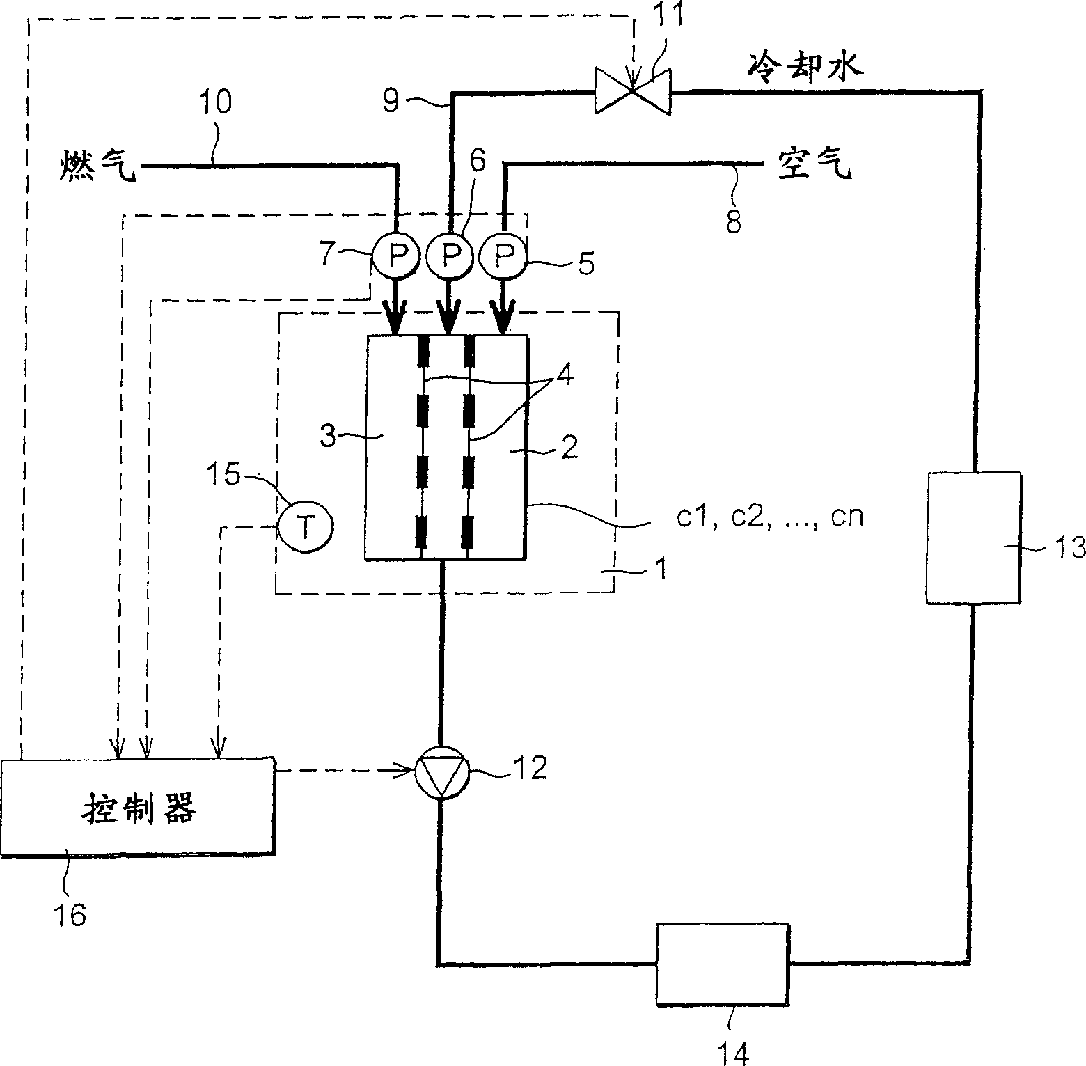
[0022] see attached figure 1 , the fuel cell system related to the present invention is equipped with: a fuel cell stack 1 including many cells c1, c2..., cn, pressure sensors 5, 6, 7, cooling water pump 12, cooling water tank 13, heat exchanger 14, and control device 16. The temperature sensor 15 is used to measure the internal temperature Tsin of the fuel cell stack 1 and is installed inside the fuel cell stack 1 . Measurement signals from these sensors are input to the controller 16 .

[0023] The pressure sensors 5, 6, 7 measure the pressure near the inlet of the fuel cell stack 1 in the air channel 8 for inputting air to the fuel cell stack 1, the cooling water channel 9 for inputting cooling water, and the gas channel 10 for inputting gas.

[0024] Controller 16 includes one, two or more microprocessors, a memory and an input / output interface. The controller 16 calculates the pressure difference ΔP between the cooling water channel 9 and the electrodes—negative electr...


PUM


Abstract

Before warmup of a fuel cell stack (1) is complete, a cooling water pressure of the fuel cell stack (1) is suppressed lower than the pressure used when the fuel cell system is run in the steady state. In this way, when the system is started from a low temperature state, water in a cathode (2) and anode (3) flows efficiently into the cooling water passage (9), and water clogging is prevented while maintaining a proper water balance in the fuel cell system.

Description

technical field [0001] The present invention relates to fuel cell systems, and more particularly, to start-up control when starting a fuel cell system from a low temperature state. Background technique [0002] Fuel cells convert the energy of fuel directly into electricity. In the fuel cell system disclosed in JP8-106914A published by the Japan Patent Office in 1996, in a pair of electrodes on both sides of the membrane electrode, hydrogen-containing gas is supplied to the positive electrode and oxygen-containing oxidant gas is supplied to the negative electrode. The electrical energy is then released from the electrodes using the electrochemical reactions that take place on the surface of the membrane electrodes, namely: [0003] Positive reaction: <chemistry num="001"> <chem file="02802716_cml001.xml" / > < / chemistry> [0004] Negative reaction: <chemistry num="002"> <chem file="02802716_cml002.xml" / > < / chemistry> [0005] The ...

Claims


Application Information

Patent Timeline
Patent Type & Authority Patents(China)
IPC IPC(8): H01M8/04H01M8/06H01M8/10
CPCH01M8/04119Y02E60/50H01M8/04029H01M8/04223H01M8/0267H01M8/241H01M8/04225H01M8/04302H01M8/2457H01M8/04
Inventor 高桥真一吉泽幸大
Owner NISSAN MOTOR CO LTD
Why Eureka
Try Eureka