Positioning puncture device for intestinal surgery
A technique for intestinal surgery and operation, which is applied in the field of positioning and puncturing devices for intestinal surgery, can solve the problems of difficulty in grasping the puncture depth and low operation precision, and achieves the effects of good stability, reduced pain, and prevention of low manual operation precision.
- Summary
- Abstract
- Description
- Claims
- Application Information
AI Technical Summary
Problems solved by technology
Method used
Image
Examples
Embodiment 1
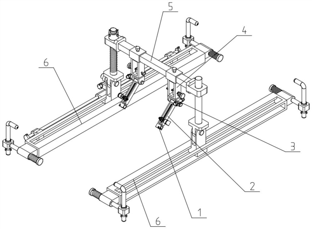
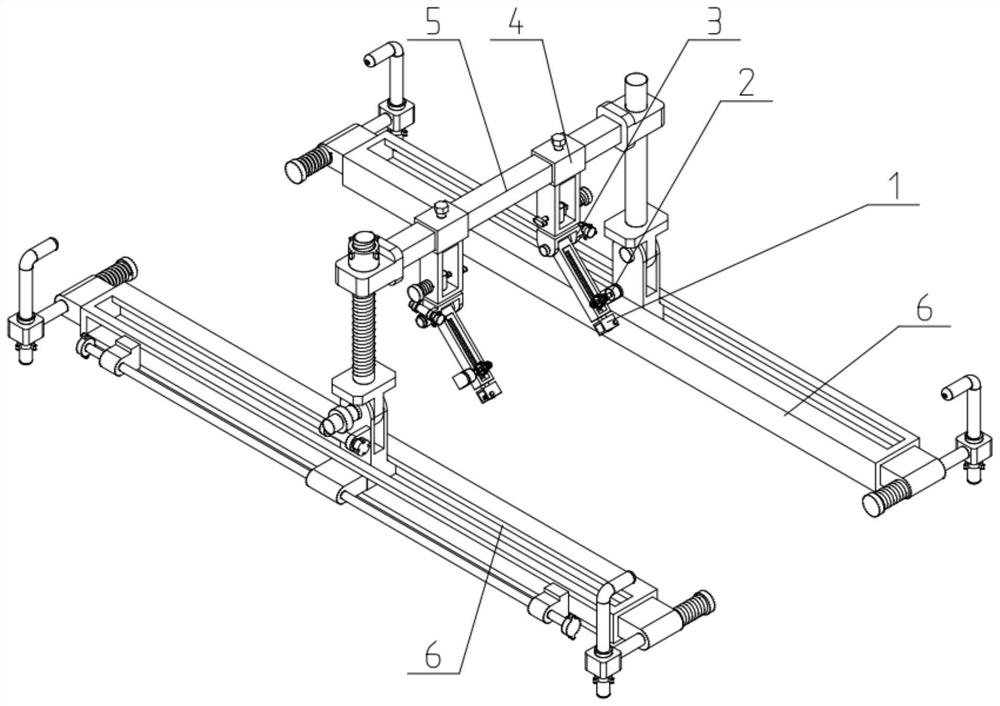
[0035] Such as Figure 1-10 As shown, a positioning puncture device for intestinal surgery includes a puncture tube base 1, a puncture control mechanism 2, a puncture angle adjustment mechanism 3, a sliding hanger mechanism 4, a sliding bracket mechanism 5 and a chute frame mechanism 6; the puncture The tube base 1 is connected to the lower end of the puncture control mechanism 2, and the upper end of the puncture control mechanism 2 is connected to the puncture angle adjustment mechanism 3; the puncture angle adjustment mechanism 3 is connected to the sliding hanger mechanism 4 above; the sliding hanger mechanism 4 is slidably fitted on the sliding bracket mechanism 5; the sliding bracket mechanism 5 is slidably fitted on the two chute frame mechanisms 6; the two chute frame mechanisms 6 are opposite It is set and fixed on both ends of the operating bed by clamping. A positioning puncture device for intestinal surgery of the present invention can be installed on both ends of...
Embodiment 2
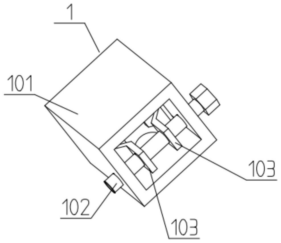
[0037] Such as Figure 1-10 As shown, the puncture tube base 1 includes a tube base body 101, a two-way screw 102 and a sliding clamp block 103; the upper end of the tube base body 101 is fixed on the puncture control mechanism 2, and the lower end of the tube base body 101 is provided with a tube hole, the inner side of the pipe hole is slidably fitted to connect the puncture tube; the inner side of the tube base body 101 is slidably connected to two sliding clamps 103, and the two sliding clamps 103 are threadedly fitted on the two ends of the two-way screw 102, and the two-way screw 102 is rotatably fitted on the tube base body 101; the tube hole is located between the two V-shaped clip grooves of the two sliding clamp blocks 103. The puncture tube base 1 is used to clamp and fix the puncture tube, and the two sliding clamps 103 can be driven to slide inside the tube base body 101 by rotating the two-way screw 102 to adjust the distance between the two sliding clamps 103 ,...
Embodiment 3
[0039] Such as Figure 1-10 As shown, the puncture control mechanism 2 includes an overturn frame 201, a rack 202, a gear 203, a wheel shaft 204 and a servo motor 205; one end of the overturn frame 201 is fixedly connected to the puncture angle adjustment mechanism 3, and the overturn The other end of the rack 201 is provided with a rectangular through hole slidingly fitted in the middle of the rack 202, the lower end of the rack 202 is fixedly connected with the socket body 101, and the upper end of the rack 202 is meshed with the gear 203 for transmission connection; the gear 203 passes through the axle 204 is rotatably fitted on the lower end of the reversing frame 201; the output shaft of the servo motor 205 fixed on the reversing frame 201 through the motor bracket is connected to the wheel shaft 204 through a coupling transmission. When the puncture control mechanism 2 is in use, its inclination angle can be adjusted through the puncture angle adjustment mechanism 3, and...
PUM
 Abstract
Description
Claims
Application Information
 - R&D
- Intellectual Property
- Life Sciences
- Materials
- Tech Scout
- Unparalleled Data Quality
- Higher Quality Content
- 60% Fewer Hallucinations
Browse by: Latest US Patents, China's latest patents, Technical Efficacy Thesaurus, Application Domain, Technology Topic, Popular Technical Reports.
© 2025 PatSnap. All rights reserved.Legal|Privacy policy|Modern Slavery Act Transparency Statement|Sitemap|About US| Contact US: help@patsnap.com


