Mixed coating stirring device

A stirring device and a technology for mixing paints, which are used in mixers, mixer accessories, mixers with rotating containers, etc., can solve the problems of physical effort, troublesome cleaning, uneven mixing, etc.

Pending Publication Date: 2021-06-04
熊建平
View PDF5 Cites 1 Cited by
  • Summary
  • Abstract
  • Description
  • Claims
  • Application Information

AI Technical Summary

Problems solved by technology

[0005] In order to overcome the disadvantages that manual stirring is very easy to cause cleaning troubles, and it is very labor-intensive and easy to cause uneven stirring, the technical problem is: to provide a stirring device that can automatically and evenly mix paint

Method used


Image

  • Mixed coating stirring device
  • Mixed coating stirring device
  • Mixed coating stirring device

Examples


Embodiment 1

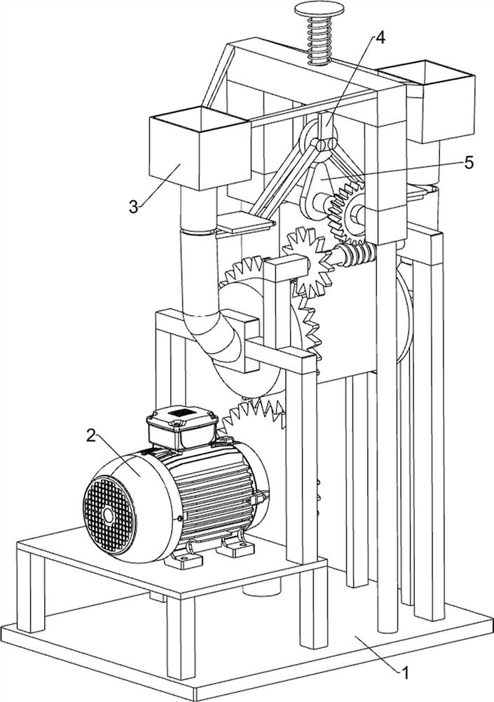
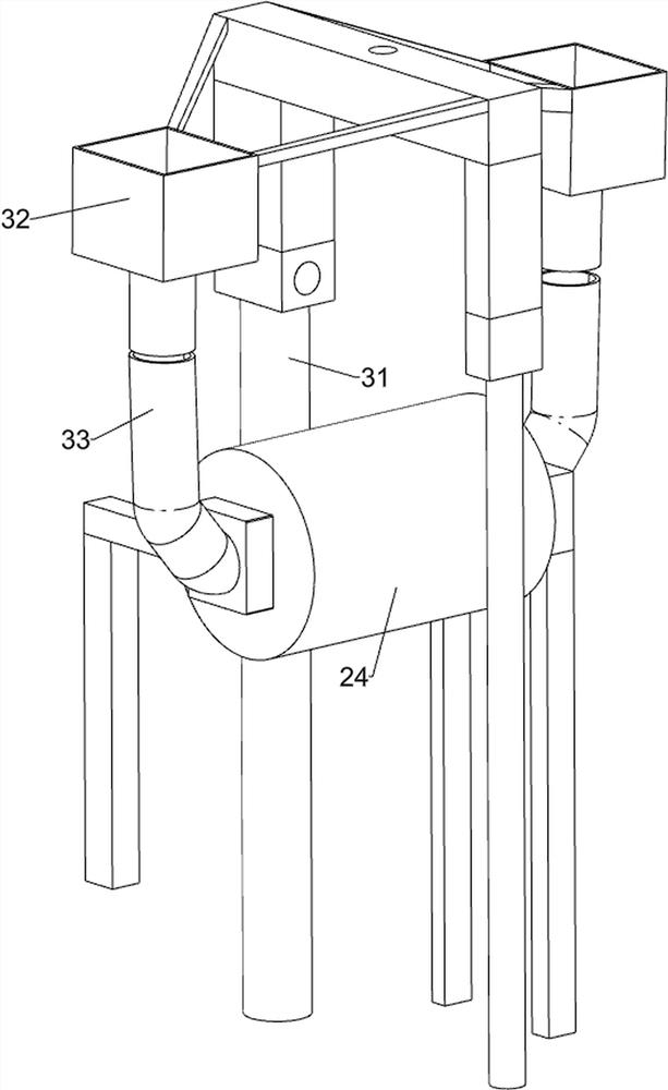
[0023] A stirring device for mixing paint, such as Figure 1-3 As shown, it includes a support frame 1 , a mixing assembly 2 and a blanking assembly 3 , the mixing assembly 2 is provided on the front upper side of the support frame 1 , and the blanking assembly 3 is provided on the upper side of the support frame 1 .

[0024] When the paint needs to be stirred, start the mixing component 2, then put the paint into the feeding component 3, the paint will enter the mixing component 2 through the feeding component 3, and the mixing component 2 will stir the paint at the same time, and the stirring is completed After that, close the mixing component 2.

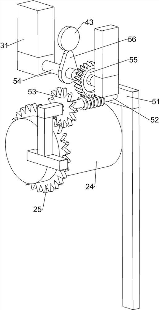
[0025] The mixing assembly 2 includes a reduction motor 21, a first gear 22, a first support 23, a rotating drum 24 and a second gear 25, and the upper side of the front part of the support frame 1 is fixed with a reduction motor 21 by bolts, and the output of the reduction motor 21 The first gear 22 is connected to the shaft, th...

Embodiment 2

[0030] On the basis of Example 1, such as figure 1 , Figure 4 and Figure 5 As shown, a blocking assembly 4 is also included, and the blocking assembly 4 includes a guide rod 41, a spring 42, a disk 43, a connecting rod 44, a baffle plate 45 and a slide rail 46, and the second bracket 31 is slidably provided with a guide rod 41 A spring 42 is connected between the guide rod 41 and the second bracket 31, the underside of the guide rod 41 is connected with a disc 43, and the inside of the feeding pipe 33 is connected with a slide rail 46, and the slide rail 46 is provided with sliding The baffle 45 is rotatably provided with a connecting rod 44 between the baffle 45 and the disc 43 .

[0031] After the paint is put into the storage boxes 32 on both sides, the guide rod 41 can be controlled to move upwards, so that the spring 42 is stretched, and at the same time, the disc 43 is driven to move upwards, and the connecting rod 44 drives the baffle plates 45 on both sides to move...


PUM


Abstract

The invention relates to a stirring device, in particular to a mixed coating stirring device. The technical problem to be solved by the invention is to provide the mixed coating stirring device capable of achieving automatic and uniform stirring. The mixed coating stirring device comprises: a support frame; a mixing assembly, which is mounted on the support frame; and a blanking assembly, which is installed on the support frame. By controlling a speed reducing motor, a rotating drum automatically rotates and stirs, the operation is simple and convenient, and the device can be used for mass production; the stirring device is provided with a blocking assembly, so that a storage frame can be prevented from being blocked, coating in the storage frame cannot completely flow into a rotary drum to be stirred, and the situation that the stirring effect is affected due to excessive feeding is effectively prevented; the device is provided with an automatic switch assembly, so that the device can achieve automatic and uniform blanking, the coating is stirred more uniformly, meanwhile, the device can performing blanking without manually controlling the blocking assembly, and manpower is saved.

Description

technical field [0001] The invention relates to a stirring device, in particular to a mixing paint stirring device. Background technique [0002] The paint has a wide range of functions in life. When one of the colors is not available, it can be configured by mixing the paint, so it is necessary to mix the paint and stir. [0003] Generally, the mixed paint is mixed manually. When mixing manually, it is necessary to manually pour the two paints into a bucket, and then rotate and stir with a stick in hand. It is very easy to splash the paint on the body or the ground during manual stirring. Thereby causing cleaning trouble, and manual stirring is very labor-intensive, and it is easy to cause uneven stirring. [0004] Therefore need to design a kind of mixing paint stirring device that can automatically and stir evenly. Contents of the invention [0005] In order to overcome the disadvantages that manual stirring is very easy to cause cleaning troubles, consumes a lot of p...

Claims


Application Information

Patent Timeline
IPC IPC(8): B01F9/02B01F15/02B01F29/60
CPCB01F29/60B01F35/71715B01F35/717B01F2101/30
Inventor 熊建平
Owner 熊建平
Why Eureka
Try Eureka