Shearing assembly and shearing machine

A component and knife component technology, which is applied in the direction of shearing device, shearing machine equipment, metal processing equipment, etc., can solve the problems of blade wear and other problems, and achieve the effects of reducing abnormal wear, high production efficiency and high shearing efficiency

Active Publication Date: 2021-06-04
长沙中金智能装备有限公司
View PDF10 Cites 9 Cited by
  • Summary
  • Abstract
  • Description
  • Claims
  • Application Information

AI Technical Summary

Problems solved by technology

This type of shearing machine has the following defects: reference figure 1 The cutting edge 11 of the moving knife 10 and the cutting edge 21 of the fixed knife 20 are concave-convex and opposite to each other. When the moving knife structure or the fixed knife structure is subjected to lateral displacement due to force, it may cause abnormal wear of the blade.

Method used


Image

  • Shearing assembly and shearing machine
  • Shearing assembly and shearing machine
  • Shearing assembly and shearing machine

Examples


Embodiment Construction

[0034] The following are specific embodiments of the application and in conjunction with the accompanying drawings, further describe the technical solution of the application, but the application is not limited to these embodiments. In the following description, specific details, such as specific configurations and components, are provided only to help a comprehensive understanding of the embodiments of the present application. Accordingly, those of ordinary skill in the art should recognize that various changes and modifications of the embodiments described herein can be made without departing from the scope and spirit of the application. Also, descriptions of well-known functions and constructions are omitted for clarity and conciseness.

[0035] It should be noted that, in the case of no conflict, the implementations in the present application and the features in the implementations can be combined with each other.

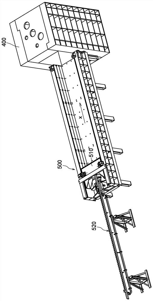
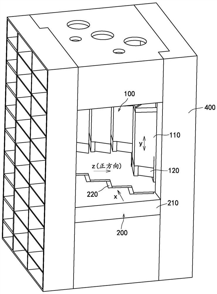
[0036] refer to Figure 2 to Figure 8 , the embodiment ...


PUM


Abstract

The invention provides a shearing assembly and a shearing machine, and relates to the technical field of shearing machines. The shearing assembly comprises a movable cutter assembly, a fixed cutter assembly and a power source; the movable cutter assembly comprises a movable cutter holder and a movable cutter installed on the movable cutter holder; the movable cutter is provided with a shearing cutting edge consisting of a transverse cutting edge and a longitudinal cutting edge; and the orthographic projection of the shearing cutting edge in the y-axis direction is in a step shape. The y-axis direction is the moving direction of the movable cutter assembly; the longitudinal cutting edge is provided with a front end close to the feeding side and a rear end close to the discharging side; and in the z-axis direction, the front end and the rear end are the same in position or the rear end is located in the positive direction of the front end. The z-axis direction is perpendicular to the x-axis direction and the y-axis direction; the x-axis direction is a feeding direction; in the z-axis direction, the direction from the fixed cutter to the movable cutter is set to be the positive direction; and according to the shearing assembly, on the basis that the step-shaped shearing cutting edge is adopted, the material can be sheared into a plurality of blocks at a time, and higher production efficiency is achieved.

Description

technical field [0001] The present application relates to the technical field of shearing machines, in particular to a shearing assembly and a shearing machine. Background technique [0002] The shearing machine is suitable for metal recycling processing plants, scrapped car dismantling sites, smelting and casting industries, for cold shearing, pressing and flanging of various shapes of steel and various metal materials, as well as powder products, plastics, glass steel, insulation, etc. Press molding of materials and rubber. The most commonly used metal shears are crocodile shears and gantry shears. [0003] The scrap steel shearing machine is provided with two blade assemblies, and the material is cut through the relative movement of the two blade assemblies. Some scrap steel shearing machines use bent blades to cut materials. For example, Chinese patent 201310704426.0 discloses a stepped combined shearing edge, which consists of an upper shearing edge and a lower sheari...

Claims


Application Information

Patent Timeline
Patent Type & Authority Applications(China)
IPC IPC(8): B23D15/04
CPCB23D15/04
Inventor 杨岱璋沈湘洪费望龙曹赛华
Owner 长沙中金智能装备有限公司
Why Eureka
Try Eureka