Supercharge Your Innovation With Domain-Expert AI Agents!

Feeding mechanism of laser cutting machine

A laser cutting machine and feeding technology, which is applied to laser welding equipment, manufacturing tools, and other household appliances, can solve the problems of high cost, low efficiency, and poor reliability, and achieve a space-saving, high-efficiency, and low-cost solution. Effect

Pending Publication Date: 2021-06-04
开平力蒲卫浴有限公司
View PDF5 Cites 0 Cited by
  • Summary
  • Abstract
  • Description
  • Claims
  • Application Information

AI Technical Summary

Problems solved by technology

According to the prior art, there is a feeding mechanism of a round pipe cutting machine. The discharge frame is arranged obliquely. Only when the steel pipes are laid flat on the discharge frame can the automatic feeding of the round pipes be realized. That is to say, the steel pipes cannot be stacked together in multiple rows. In this way, only a small amount of round tubes can be placed on the discharge rack for loading at one time, and the efficiency is low. If a large number of round tubes are to be placed on the discharge rack, the width of the discharge rack needs to be enlarged, which takes up space and costs a lot. ; There is also an automatic feeding cutting machine. Although the storage rack can place multiple rows of steel pipes, because the storage rack is also inclined, the steel pipes roll to the position of the feeding push cylinder by gravity. , the steel pipes will interfere with each other when the feeding push cylinder pushes the steel pipes, and the reliability is poor

Method used


Image

  • Feeding mechanism of laser cutting machine
  • Feeding mechanism of laser cutting machine
  • Feeding mechanism of laser cutting machine

Examples


Embodiment Construction

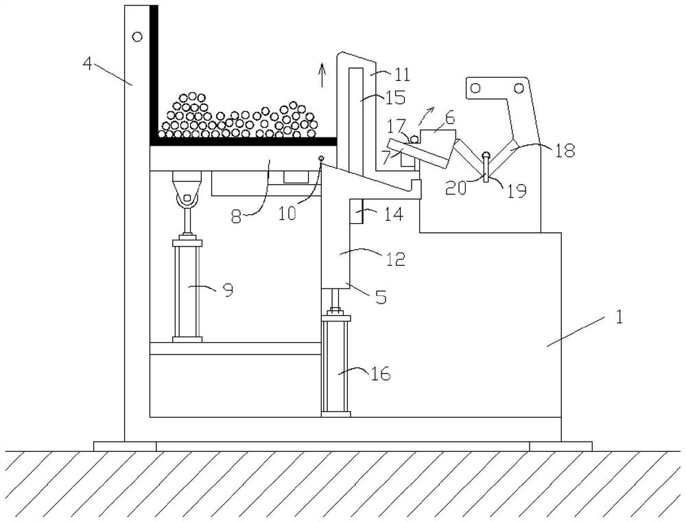
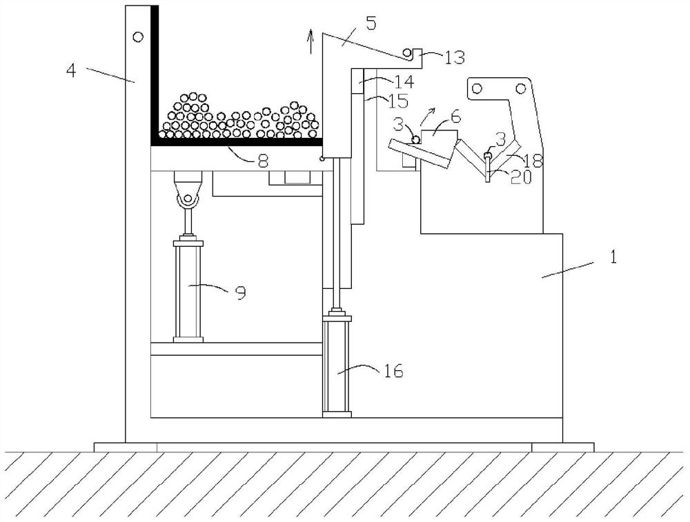
[0027] The present invention will be further described below in conjunction with the accompanying drawings and specific embodiments.

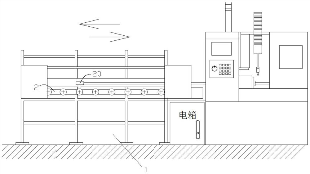
[0028] Such as figure 1 and 2 As shown, the present invention provides a feeding mechanism for a laser cutting machine, including a conveyor frame 1, a conveyor chain 2 on the conveyor frame 1, a top material frame 5 and a transition mechanism, and an object frame 4 is provided on the left side of the conveyor frame 1 , a plurality of pipe fittings 3 are arranged in the storage rack 4, and the opening on the right side of the storage rack 4 is convenient for the top material rack 5 to enter the storage rack 4 to eject the pipe fittings 3. Rolling down from the opening of the rack 4, the jacking rack 5 is arranged between the rack 4 and the conveying frame 1, and the left end of the jacking rack 5 stretches out from the left side of the baffle plate 11, so that the jacking rack 5 moves upwards When the single pipe fitting 3 is pushed up, the p...


PUM


Abstract

The invention discloses a feeding mechanism of a laser cutting machine. The feeding mechanism comprises a conveying rack, a conveying chain arranged on the conveying rack, a storage rack for containing a plurality of pipe fittings, a jacking rack for taking the pipe fittings, a plurality of baffles and a transition mechanism, wherein the storage rack is located on the left side of the conveying rack, the baffles are arranged on the right side of the storage rack, the jacking rack is arranged between the storage rack and the conveying rack, and the left end of the jacking rack extends out of the left side faces of the baffles. When the jacking rack moves upwards to the position below the upper surfaces of the baffles, the left end of the jacking rack jacks out the pipe fittings in the storage rack one by one, and when the jacking rack moves to the position above the upper surfaces of the baffles, the pipe fittings move from the left end of the jacking rack to the right end of the jacking rack, and are transferred to the conveying chain from the right end of the jacking rack through the transition mechanism. The feeding mechanism of the laser cutting machine is high in efficiency, small in occupied space, low in cost and high in reliability.

Description

technical field [0001] The invention relates to the technical field of cutting machines, in particular to a feeding mechanism of a laser cutting machine. Background technique [0002] Laser cutting is realized by applying high power density energy generated by laser focusing. It can be widely used in metal material processing. It has the characteristics of narrow incision width, small heat-affected zone, smooth incision, high cutting speed, and can cut any shape at will. . Use the laser cutting machine to cut the pipe fittings, and send the pipe fittings to the laser cutting machine for cutting through the conveyor chain. According to the prior art, there is a feeding mechanism of a round pipe cutting machine. The discharge rack is arranged obliquely. Only when the steel pipes are laid flat on the discharge rack can the automatic feeding of the round pipes be realized. That is to say, the steel pipes cannot be stacked together in multiple rows. In this way, only a small am...

Claims


Application Information

Patent Timeline
Patent Type & Authority Applications(China)
IPC IPC(8): B23K26/70B23K26/38B23K101/06
CPCB23K26/702B23K26/38B23K2101/06
Inventor 邝忠胜
Owner 开平力蒲卫浴有限公司
Features
  • R&D
  • Intellectual Property
  • Life Sciences
  • Materials
  • Tech Scout
  • Unparalleled Data Quality
  • Higher Quality Content
  • 60% Fewer Hallucinations
Learn More