Automatic pipe inserting device for air valve

A gas valve and intubation technology, applied in the field of gas valve automatic intubation devices, can solve the problems of restricting production efficiency, difficulty in aligning the gas valve and the trachea, and low work efficiency

Active Publication Date: 2021-06-04
欧恩科(北京)自动门科技有限公司
View PDF12 Cites 0 Cited by
  • Summary
  • Abstract
  • Description
  • Claims
  • Application Information

AI Technical Summary

Problems solved by technology

[0002] At present, in the production process of air valve intubation, the process of inserting the trachea into the air valve is still a manual operation. Manually inserting the trachea one by one into the air valve requires precise alignment for successful intubation, and a slight deviation will result in intubation failure. , that is, the alignment of the air valve and the air pipe is difficult
For the smaller trachea, it is more difficult to insert. At present, such precise alignment technology cannot be achieved, so at present, only manual intubation can be used, which leads to low work efficiency and high labor intensity, which seriously restricts production efficiency.
[0003] The air pipe is connected to the air valve, and the mouth of the pipe is sealed by interference fit. At present, manual assembly is used in the installation process. Due to the tight fit of the assembly method, the friction force is relatively large during assembly, and more force is required to assemble. in place
As the current air valve assembly is mass-produced on an assembly line, the production line is full-time production, and the labor intensity of the operation is relatively high. Ordinary operators are not competent, and the installation generally cannot be completed at one time.

Method used


Image

  • Automatic pipe inserting device for air valve
  • Automatic pipe inserting device for air valve
  • Automatic pipe inserting device for air valve

Examples


Embodiment Construction

[0023] The following will clearly and completely describe the technical solutions in the embodiments of the present invention with reference to the accompanying drawings in the embodiments of the present invention. Obviously, the described embodiments are only some, not all, embodiments of the present invention. Based on the embodiments of the present invention, all other embodiments obtained by persons of ordinary skill in the art without making creative efforts belong to the protection scope of the present invention.

[0024] The purpose of the present invention is to provide an air valve automatic intubation device to solve the above-mentioned problems in the prior art and improve the efficiency of air valve intubation.

[0025] In order to make the above objects, features and advantages of the present invention more comprehensible, the present invention will be further described in detail below in conjunction with the accompanying drawings and specific embodiments.

[0026...


PUM


Abstract

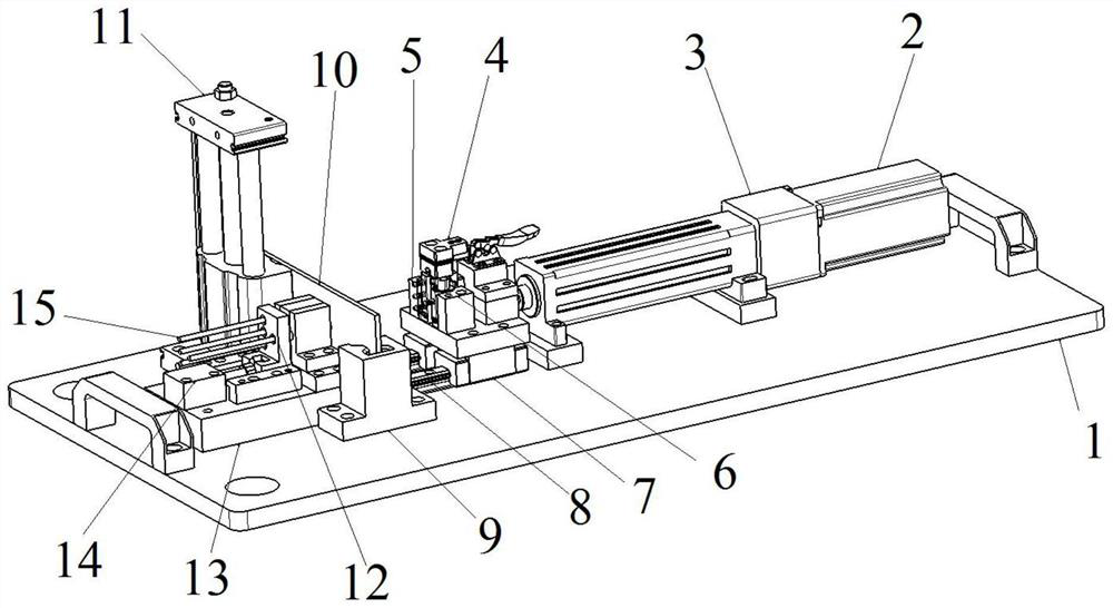
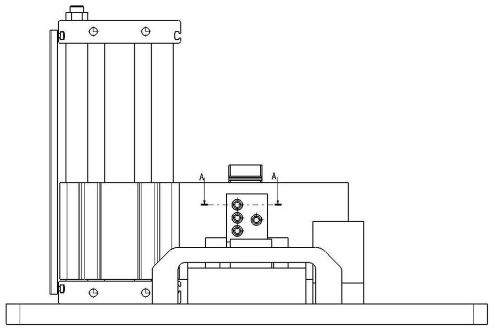
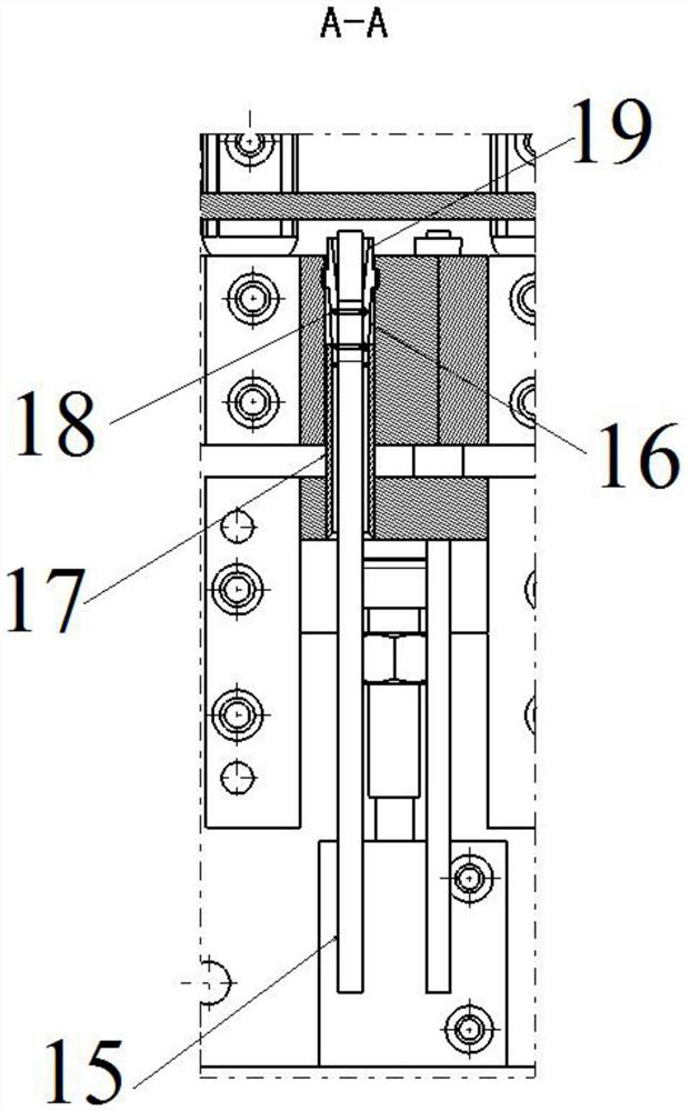
The invention discloses an automatic pipe inserting device for an air valve, which comprises a base plate, and a servo electric cylinder used for driving a first sliding block to slide along a first sliding rail, a translation air cylinder used for driving a second sliding block to slide along a second sliding rail and a lifting air cylinder used for driving a vertical baffle to ascend and descend are arranged on the base plate. The first sliding rail and the second sliding rail are flatly laid on the base plate, the baffle is located between the first sliding block and the second sliding block, a fixing block located between the second sliding block and the baffle is further fixedly arranged on the base plate, a plurality of positioning holes used for clamping an air pipe are formed in the second sliding block, and through holes corresponding to the positioning holes in a one-to-one mode are formed in the fixing block. Two clamping petals are arranged in each through hole, a sleeve is fixedly arranged at the end, close to the corresponding fixing block, of each positioning hole, a draft slope is arranged at the end, close to the corresponding sleeve, of each clamping petal, and an air valve tool is arranged on the first sliding block. According to the automatic pipe inserting device for the air valve, the pipe inserting efficiency of the air valve is greatly improved.

Description

technical field [0001] The invention relates to the technical field of gas valve intubation equipment, in particular to an automatic gas valve intubation device. Background technique [0002] At present, in the production process of air valve intubation, the process of inserting the trachea into the air valve is still a manual operation. Manually inserting the trachea one by one into the air valve requires precise alignment for successful intubation, and a slight deviation will result in intubation failure. , that is, the alignment of the air valve and the air pipe is difficult. For smaller trachea, it is more difficult to insert, and such precise alignment technology is not yet available, so at present, manual intubation can only be used, which leads to low work efficiency and high labor intensity, which seriously restricts production efficiency. [0003] The air pipe is connected to the air valve, and the mouth of the pipe is sealed by interference fit. At present, manual...

Claims


Application Information

Patent Timeline
IPC IPC(8): B23P19/02B23P19/00
CPCB23P19/022B23P19/006
Inventor 张明
Owner 欧恩科(北京)自动门科技有限公司
Why Eureka
Try Eureka