Mutual control reversing action circuit of double-direct-current railway signal switch machine
A technology of railway signal and switch machine, which is applied in railway signal, railway signal and safety, remote control signal and other directions, can solve the problem that the test cannot be continued, and achieve the effect of scientific structure design and long service life.
- Summary
- Abstract
- Description
- Claims
- Application Information
AI Technical Summary
Problems solved by technology
Method used
Image

Examples
Embodiment 1
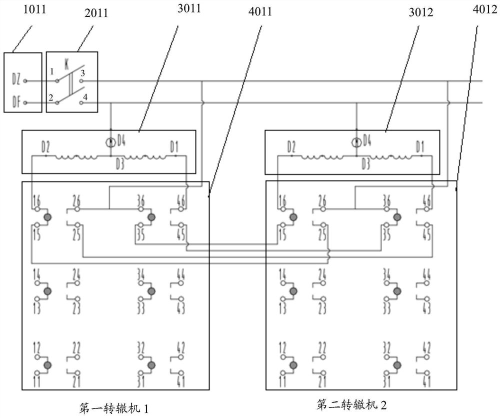
[0119] In the present invention, in terms of specific implementation, the circuit of the present invention, the circuit structure of Embodiment 1 is as follows figure 1 Shown, in embodiment one, adopt a DC power supply, carry out the run-in test (being run-in test) or life test of two DC point machines under the same power supply voltage condition;
[0120] see figure 1 As shown, when the external DC voltage only includes a first DC power supply 1011, the power supply output line of the first DC power supply 1011 is provided with a first main control switch 2011;
[0121] The voltage output terminal DZ and the voltage output terminal DF of the first DC power supply 1011 are respectively connected to the movable contact 1 and the movable contact 2 of the first main control switch 2011;
[0122] For the first main control switch 2011, it includes a static contact 3 and a static contact 4, and the static contact 3 and the static contact 4 are respectively set corresponding to th...
Embodiment 2
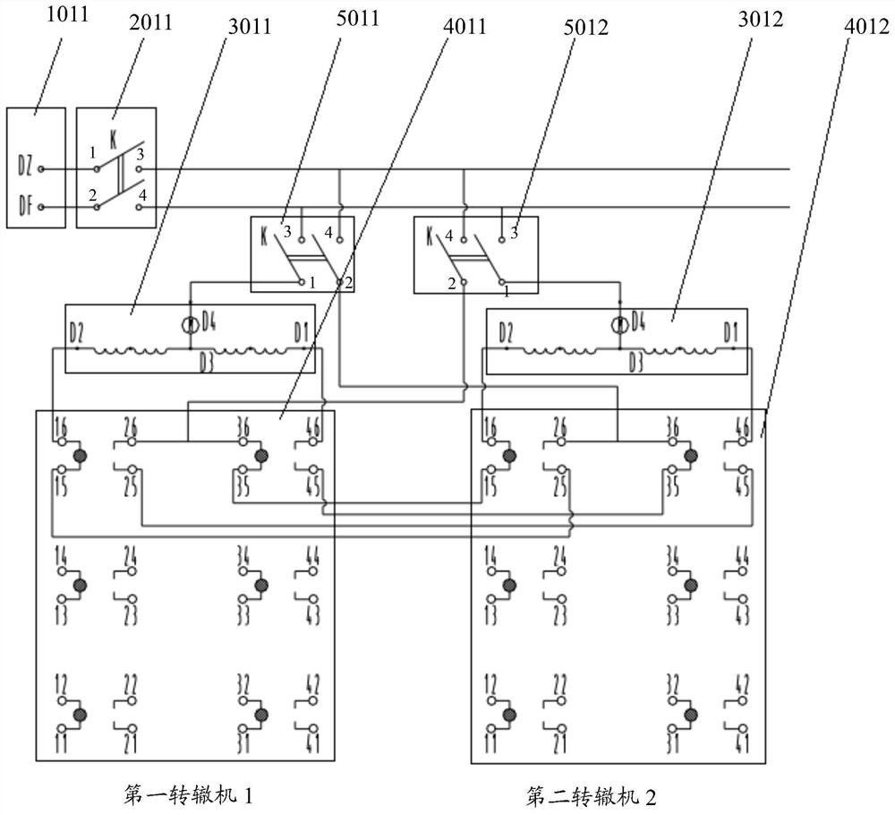
[0146] In the present invention, in specific implementation, the circuit of the present invention, the circuit structure of the second embodiment is as follows figure 2 As shown, in Embodiment 2, a DC power supply is used, and an auxiliary control switch is configured for each DC point machine, and the running-in test (that is, the running-in test) of two point machines under the same power supply voltage condition is carried out. or life test;
[0147] see figure 2 As shown, when the external DC voltage only includes a first DC power supply 1011, the power supply output line of the first DC power supply 1011 is provided with a first main control switch 2011;
[0148] The voltage output terminal DZ and the voltage output terminal DF of the first DC power supply 1011 are electrically connected to the movable contact 1 and the movable contact 2 of the first main control switch 2011 respectively;
[0149] For the first main control switch 2011, it includes a static contact 3 ...
Embodiment 3
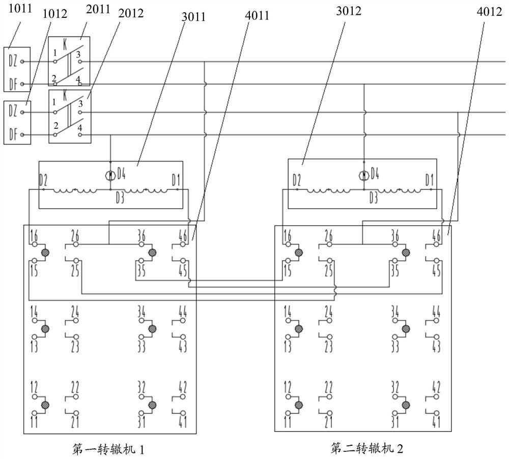
[0159] In the present invention, in terms of specific implementation, the circuit of the present invention, the circuit structure of the third embodiment is as follows image 3 As shown, in the third embodiment, two DC power supplies are used to carry out the running-in test (ie running-in test) or life test of two DC point machines under different power supply voltage conditions.
[0160] see image 3 As shown, when the external DC voltage includes two DC power sources, the first DC power source 1011 and the second DC power source 1012, the power supply output lines of the first DC power source 1011 and the second DC power source 1012 are respectively provided with first Main control switch 2011 and second main control switch 2012;
[0161] Wherein, the voltage output terminal DZ and the voltage output terminal DF of the first DC power supply 1011 are respectively connected with the movable contact 1 and the movable contact 2 of the first main control switch 2011;
[0162] ...
PUM
 Abstract
Description
Claims
Application Information
 - Generate Ideas
- Intellectual Property
- Life Sciences
- Materials
- Tech Scout
- Unparalleled Data Quality
- Higher Quality Content
- 60% Fewer Hallucinations
Browse by: Latest US Patents, China's latest patents, Technical Efficacy Thesaurus, Application Domain, Technology Topic, Popular Technical Reports.
© 2025 PatSnap. All rights reserved.Legal|Privacy policy|Modern Slavery Act Transparency Statement|Sitemap|About US| Contact US: help@patsnap.com