
Automatic strapping device and automatic strapping method for copper rods

A technology of automatic bundling and copper rods, which is applied in the directions of bundling materials, automatic packaging control, and parts of bundling machinery, etc., can solve the problems of time-consuming and laborious copper rods, difficult to lift and transport, and coils are easy to cross each other, so as to reduce labor costs. Effect

Pending Publication Date: 2021-06-04
成都金中机械设备制造有限公司
View PDF1 Cites 0 Cited by
  • Summary
  • Abstract
  • Description
  • Claims
  • Application Information

AI Technical Summary

Problems solved by technology

[0002] At present, after the copper rods are produced by the production line, they are rolled out through the last rolling mill and then coiled by the rod receiving equipment. Since the coils are very scattered after the coils are harvested, it is difficult to lift them, that is, they need to be rolled The copper rod coil is bundled with three self-produced copper rods at intervals of 120° along its circumference. At present, it is operated manually, and the manual reaming of the copper rod is time-consuming and laborious, which is very inconvenient. Patent No. CN201811052441.0 discloses a metal coil The strapping equipment and strapping method include a strapping trolley, a threading channel, a wire rod cutting mechanism arranged on the strapping trolley, a traction mechanism, a horizontal hydraulic slide table, an oblique hydraulic slide table, a vertical motion mechanism and a horizontal motion mechanism, with a compact structure, It can reduce the labor intensity of workers, improve the binding efficiency, have a high degree of automation, and bind firmly. However, due to the inconsistent technical requirements for copper rod binding, it cannot be directly applied to copper rod binding. It is easy to cross each other during hoisting, resulting in the failure to retract smoothly, so that the coil cannot be firmly tied.

Method used


Image

  • Automatic strapping device and automatic strapping method for copper rods
  • Automatic strapping device and automatic strapping method for copper rods
  • Automatic strapping device and automatic strapping method for copper rods

Examples


Embodiment Construction

[0039] The present invention will be further described below in conjunction with the accompanying drawings, but the protection scope of the present invention is not limited to the following description.

[0040] Such as Figure 1-5 Shown:

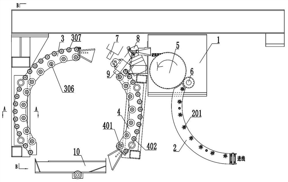
[0041] The present invention provides an automatic binding device for copper rods, including a fixing frame 1, a threading channel and a controller, wherein:

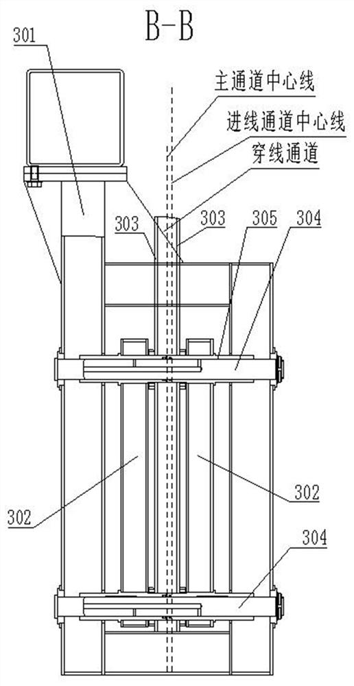
[0042] The threading channel includes an inlet channel 2 for guiding copper rods, a main channel 3 and a secondary channel 4;

[0043] A traction wheel 5 for pulling copper rods is provided between the wire inlet passage 2 and the main passage 3;

[0044] An encoder 6 for measuring the length of the copper rod is provided at the outlet of the inlet channel 2;

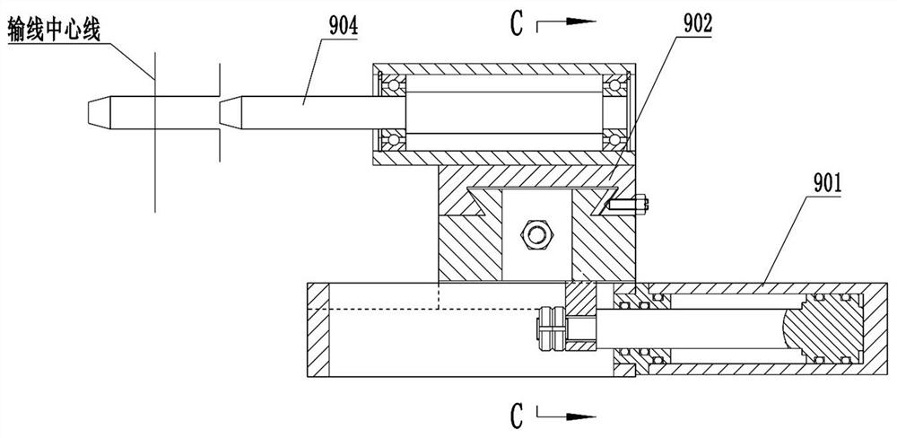
[0045] A crimping device 9 for separating the head of the copper rod is also provided between the traction wheel 5 and the main channel 3;

[0046] The traction pulley 5, the encoder 6 and the crimping device 9 are all ele...


PUM


Abstract

The invention provides an automatic strapping device and an automatic strapping method for copper rods.The automatic strapping device comprises a fixing frame (1), a threading channel and a controller, the threading channel comprises a wire inlet channel (2), a primary channel (3) and a secondary channel (4), the wire inlet channel (2) is used for guiding a copper rod, and a traction wheel (5) is arranged between the wire inlet channel (2) and the primary channel (3). An encoder (6) used for metering the threading length is further arranged beside the traction wheel (5), an indexing rotary table channel (10) communicates with the primary channel (3) and the secondary channel (4), and the center line of the primary channel (3) and the center line of the secondary channel (4) both deviate by a certain amount relative to the center line of the wire inlet channel (2). By means of the automatic strapping device, full-automatic strapping of copper rods can be achieved, hoisting of the copper rods is facilitated, the labor cost is saved, the strapping requirement of the copper rods is met, and meanwhile the situation that due to the fact that well-penetrated copper rings intersect with one another, smooth contraction cannot be achieved can be avoided.

Description

technical field [0001] The invention relates to the technical field of copper rod coil binding, in particular to an automatic copper rod binding device and an automatic binding method. Background technique [0002] At present, after the copper rods are produced by the production line, they are rolled out through the last rolling mill and then coiled by the rod receiving equipment. Since the coils are very scattered after the coils are harvested, it is difficult to lift them, that is, they need to be rolled The copper rod coil is bundled with three self-produced copper rods at intervals of 120° along its circumference. At present, it is operated manually, and the manual reaming of the copper rod is time-consuming and laborious, which is very inconvenient. Patent No. CN201811052441.0 discloses a metal coil The strapping equipment and strapping method include a strapping trolley, a threading channel, a wire rod cutting mechanism arranged on the strapping trolley, a traction mec...

Claims


Application Information

Patent Timeline
Patent Type & Authority Applications(China)
IPC IPC(8): B65B13/18B65B13/06B65B27/10B65B57/04B65B63/00
CPCB65B13/06B65B13/18B65B27/10B65B57/04B65B63/00
Inventor 钟天富
Owner 成都金中机械设备制造有限公司
Learn More