Winding equipment used for building waterproof films

A technology for building waterproofing and equipment, which is applied in the field of rolling equipment for building waterproof membranes, and can solve the problems of inconvenient replacement of rolls

Inactive Publication Date: 2021-06-04
HENAN YUZHUO INFORMATION TECH CO LTD
View PDF0 Cites 2 Cited by
  • Summary
  • Abstract
  • Description
  • Claims
  • Application Information

AI Technical Summary

Problems solved by technology

[0007] The purpose of the present invention is to provide a kind of rolling equipment for building waterproof memb

Method used


Image

  • Winding equipment used for building waterproof films
  • Winding equipment used for building waterproof films
  • Winding equipment used for building waterproof films

Examples


Embodiment 1

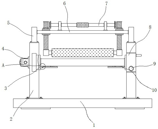
[0026] Example 1: see Figure 1-5 , a kind of winding equipment for building waterproof membrane, including base 1, side plate 2, connecting plate 5 and top plate 6, side plates 2 are fixedly connected to both sides of the top of base 1, and one side of one end of side plate 2 A cleaning structure 3 is arranged between, one end of the top of the side plate 2 is fixedly connected with a connecting plate 5, and one side of the connecting plate 5 is fixedly connected with a top plate 6, the interior of the top plate 6 is provided with a finishing structure 7, and the side plate 2 A winding mechanism is arranged between the inner sides of the

[0027] see Figure 1-5 , a winding device for building waterproof membrane also includes a winding mechanism, the winding mechanism includes a servo motor 4, the servo motor 4 is fixedly connected to the outside of the side plate 2, and the model of the servo motor 4 can be Y2-80M2-4 , the interior of one side of the side plate 2 is provi...

Embodiment 2

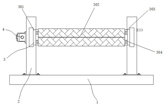
[0029] Embodiment 2: The cleaning structure 3 is composed of a fixed plate 301, a brush cylinder 302, a cavity 303 and a movable shaft 304. The fixed plate 301 is fixedly connected between one end of the side plate 2, and the interior of the fixed plate 301 is provided with a hollow space. A cavity 303, and a movable shaft 304 is movably connected to the top end and the bottom end between the two inner sides of the cavity 303 respectively, and a brush cylinder 302 is movably connected to the outside of the movable shaft 304;

[0030] The brush cylinder 302 is embedded in the interior of the fixing plate 301, and the brush cylinder 302 is symmetrically distributed about the vertical center line of the fixing plate 301;

[0031] Specifically, as figure 1 and figure 2 As shown, the conductive film is inserted through the middle gap of the fixed plate 301, so that the upper and lower ends of the cavity 303 are connected by the movable shaft 304. The brush cylinder 302 cleans the...

Embodiment 3

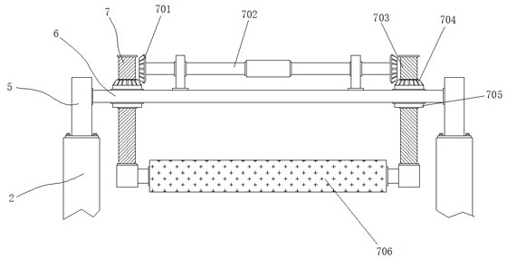
[0032] Embodiment 3: The finishing structure 7 is composed of a transverse gear 701, a rotating shaft 702, a screw 703, a longitudinal gear 704, a threaded sleeve 705 and a roller 706. The threaded sleeves 705 are respectively movably connected on both sides of the interior of the top plate 6, and the threaded sleeves 705 A longitudinal gear 704 is fixedly connected to the top of the threaded sleeve 705, a screw 703 is movably connected to the inside of the threaded sleeve 705, and a roller 706 is movably connected between one side of the bottom end of the screw 703. The rotating shaft 702 is movably connected between the two sides of the top of the top plate 6, Both sides of the rotating shaft 702 are respectively fixedly connected with transverse gears 701;

[0033] The transverse gears 701 are respectively arranged on one side of the top end of the longitudinal gears 704, and the transverse gears 701 and the longitudinal gears 704 are in the same vertical plane;

[0034] Th...


PUM


Abstract

The invention discloses winding equipment used for building waterproof films, and particularly relates to the technical field of winding equipment. The winding equipment used for the building waterproof films comprises a base, side plates, connecting plates and a top plate, wherein the side plates are fixedly connected with two sides of the top end of the base respectively, a brushing structure is arranged between one side of one end of one side plate and one side of one end of the other side plate, one corresponding connecting plate is fixedly connected with one end of the top of each side plate, the top plate is fixedly connected between one side of one connecting plate and one side of the other connecting plate, an arrangement structure is arranged in the top plate, and a winding mechanism is arranged between the inner sides of the side plates. According to the winding equipment used for the building waterproof films, the winding mechanism is arranged between the inner sides of the side plates, the winding mechanism comprises a servo motor, a handle is held to turn a turning plate outwards by 90 degrees, a winding shaft is stuffed between one side of one shaft sleeve and one side of the other shaft sleeve, the handle is loosened to make the turning plate reset under the resilience of a first spring shaft, and then clamping pieces, connected through second spring shafts, in hinge bases are shifted, so that the thin films are clamped and fixed through silica gel pads at the tops of the clamping pieces, and the purpose of facilitating replacement and installation of the winding shaft is achieved.

Description

technical field [0001] The invention relates to the technical field of rolling equipment, in particular to a rolling equipment used for building waterproof membranes. Background technique [0002] In today's construction field, people often lay waterproof membranes on walls or surfaces to prevent water from seeping into the lower layer, and the waterproof membranes need to be treated with professional equipment after some processing procedures such as melting, stretching, shaping, and drying during production. It is rolled up and sorted out, but in the past, such equipment has a single function, an old structure and low efficiency, and is no longer applicable. [0003] In the process of realizing the present invention, the inventor found that at least the following problems have not been solved in the prior art: [0004] (1) The traditional winding equipment for building waterproof membrane lacks tools to assist in fixing the waterproof membrane, and it is inconvenient to r...

Claims


Application Information

Patent Timeline
IPC IPC(8): B65H18/02B65H18/14B65H23/26B08B1/02B08B1/00
CPCB08B1/002B08B1/02B65H18/028B65H18/14B65H23/26B65H2701/10
Inventor 李阳王梦梦
Owner HENAN YUZHUO INFORMATION TECH CO LTD
Why Eureka
Try Eureka