Power cable storage device in power field

A power cable and storage device technology, which is applied in the directions of transportation and packaging, delivery of filamentous materials, thin material processing, etc., can solve the problems of low work efficiency, heavy power cables, time-consuming and labor-consuming manual storage of power cables, etc. Problems, to achieve the effect of high work efficiency

Pending Publication Date: 2021-06-04
郭茜
View PDF7 Cites 0 Cited by
  • Summary
  • Abstract
  • Description
  • Claims
  • Application Information

AI Technical Summary

Problems solved by technology

[0003] At present, when storing power cables in my country, manual storage is mostly used. Because the power cables are relatively heavy, manual storage not only needs to consume a lot of manpower and material resources, but also easily brings harm to the safety of construction workers during the storage process of power cables. , and manual storage of power cables is time-consuming and labor-intensive, and the work efficiency is low

Method used


Image

  • Power cable storage device in power field
  • Power cable storage device in power field
  • Power cable storage device in power field

Examples


Embodiment 1

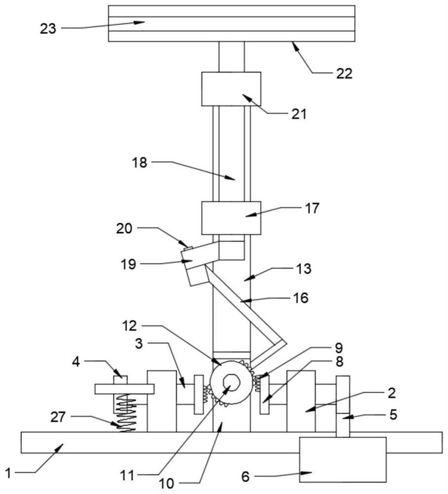
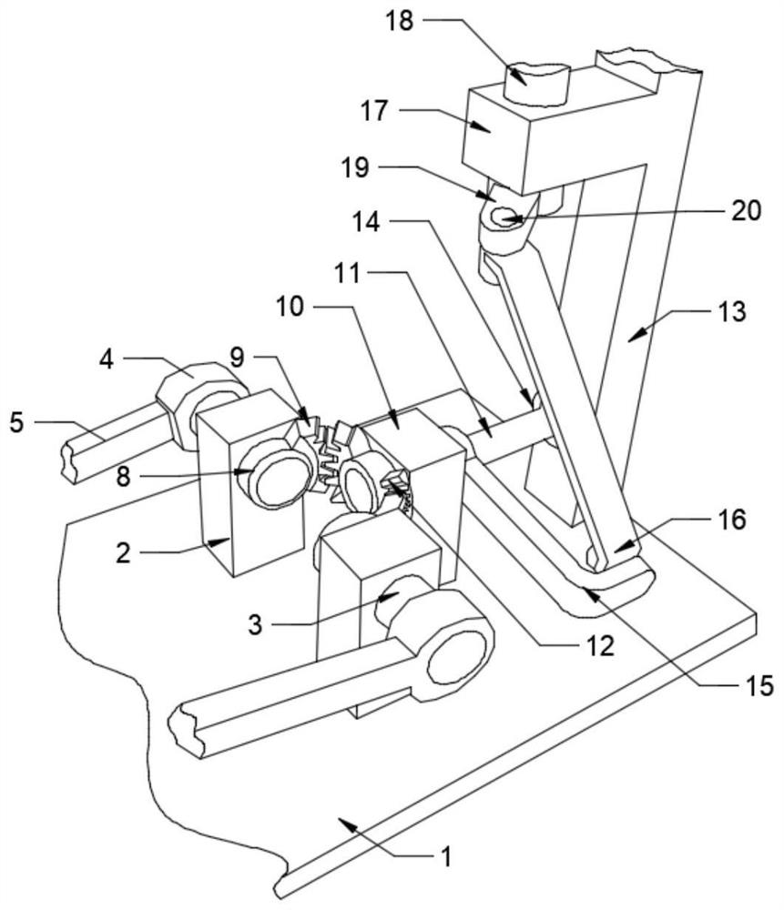
[0025] see Figure 1-5 , in an embodiment of the present invention, a power cable storage device for the electric power field, comprising: a base 1 on which a first support 2 is fixed, and a first rotating rod 3 penetrates inside the first support 2 , One end of the first rotating rod 3 is fixed with a first rotating connecting block 4, the first rotating connecting block 4 is fixedly connected with a first connecting rod 5, and the other end of the first connecting rod 5 is fixedly connected with a pedal 6, The first rotating connection block 4 runs through the other end of the first pillar 2 and is fixed with a turntable 8, and the arc-shaped rack 9 is fixedly installed on the turntable 8; the second pillar 10 is fixed on the base 1 at the same time, and the first The inside of the two pillars 10 is penetrated with a second rotating rod 11, and one end of the second rotating rod 11 passing through the second pillar 10 is fixedly installed with a first bevel gear 12, and the ...

Embodiment 2

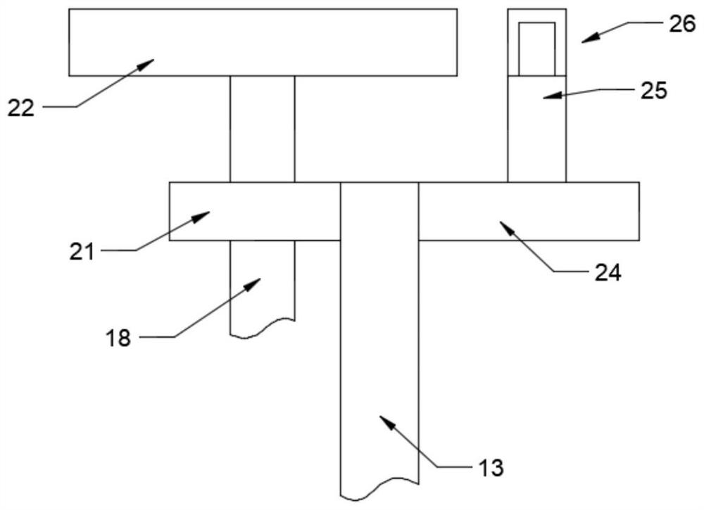
[0031] see Figure 1-5 , in this embodiment, the cable storage and cutting mechanism 26 includes: an outer frame 2601, a first chute 2602 and a second chute 2603 are arranged inside the outer frame 2601, and the first chute 2602 and the second chute A first slide plate 2606 and a second slide plate 2608 are slidably installed inside the chute 2603 respectively, and a first cutter 2607 and a second cutter 2609 are fixedly installed on the upper parts of the first slide plate 2606 and the second slide plate 2608 respectively, and the first slide plate 2606 An inner frame 2604 is fixedly connected to the lower side, a rack 2605 is fixed on one side of the inner frame 2604, a transmission shaft 2614 is arranged inside the outer frame 2601, and a second bevel gear 2613 is connected to the end of the transmission shaft 2614, The third bevel gear 2612 and the fourth bevel gear 2615 are respectively meshed on both sides of the second bevel gear 2613, and the third bevel gear 2613 and ...


PUM


Abstract

The invention relates to the technical field related to power, in particular to a power cable storage device in a power field. The power cable storage device comprises a base, a first supporting column is fixed to the base, a first rotating rod penetrates through the interior of the first supporting column, a first rotating connecting block is fixed to one end of the first rotating rod, a first connecting rod is fixedly connected to the first rotating connecting block, a pedal is fixedly connected to the other end of the first connecting rod, a rotating disc is fixed to the other end, penetrating through the first supporting column, of the first rotating connecting block, and an arc-shaped rack is fixedly mounted on the rotating disc; a second supporting column is fixed to the base at the same time, a second rotating rod penetrates through the interior of the second supporting column, a first bevel gear is fixedly mounted at the end, penetrating through the second supporting column, of the second rotating rod, a third supporting column is fixed to the other side of the base, and a rotating chassis is installed on the third supporting column. According to the device, when wires and cables are stored, the cable storage disc is rotated by treading the pedal, convenience and rapidness are achieved, and the working efficiency is high.

Description

technical field [0001] The invention relates to the technical field related to electric power, in particular to a power cable storage device for the electric power field. Background technique [0002] Power cables are cables used to transmit and distribute electric energy. They are often used in urban underground power grids, outgoing lines of power stations, internal power supply of industrial and mining enterprises, and underwater transmission lines across rivers and seas. In power lines, the proportion of cables is gradually increasing. Power cable is a cable product used to transmit and distribute high-power electric energy in the main line of the power system, including 1-500KV and above various voltage levels and various insulated power cables. With the continuous expansion of China's electric power industry, data communication industry, urban rail transit industry, automobile industry and shipbuilding and other industries, the demand for wire and cable will also grow ...

Claims


Application Information

Patent Timeline
Patent Type & Authority Applications(China)
IPC IPC(8): B65H54/44B21F11/00B65H75/14
CPCB65H54/44B21F11/00B65H75/14B65H2701/34
Inventor 郭茜
Owner 郭茜
Why Eureka
Try Eureka