
Patsnap Eureka
For R&D, Patsnap Eureka makes reading and utilizing patents & technical documents easy.
Patsnap Eureka AIR
Designed for self-driven R&D workflows. Generate viable solutions, solve complex R&D challenges, empower your innovation with AI.

Patsnap Eureka Materials
Designed for material experts only. Revolutionize your material R&D, from search, analyze, to developing new materials.

TechResearch
Generate reliable direction feasibility study reports for your R&D in just a few steps.

TechSeek
Discover and master advanced knowledge NOW. Basics, ideas, possibilities, all at once.

TechMind
As an expert in R&D Theories, TechMind can generates customized viable solutions instantly.

TechRisk
Analyze your overall solution with one click, know your potential R&D risks in advance.

TechMonitor
Get weekly tech updates, stay abreast of the latest tech innovations and key insights.
Concrete pouring equipment
A technology for concrete and equipment, applied in the field of concrete pouring equipment, can solve the problems of pouring dead corners, high cost, time-consuming, etc., and achieve the effects of improving the degree of automation, reducing material costs, and increasing work costs
- Summary
- Abstract
- Description
- Claims
- Application Information
AI Technical Summary
Problems solved by technology
Method used
Image

Examples
Embodiment 1
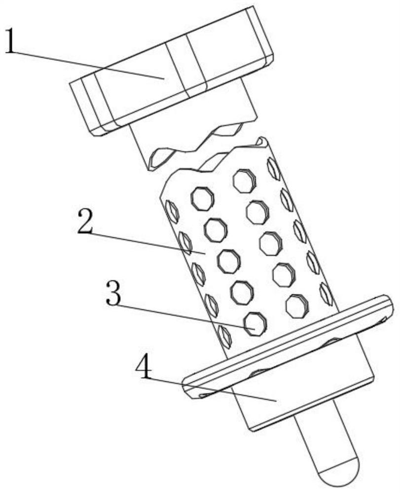
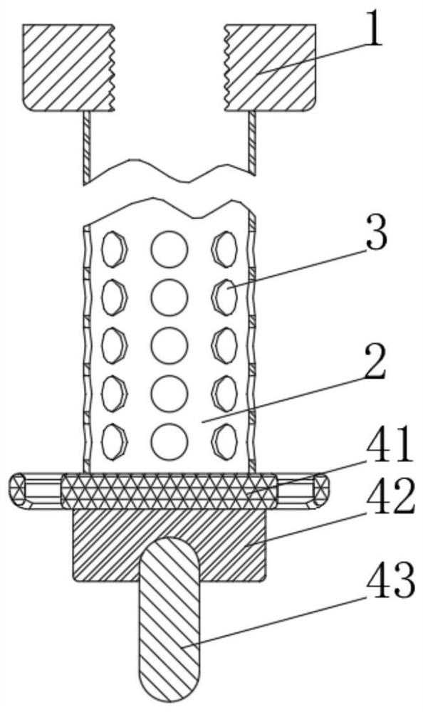
[0034] see Figure 1-2 , the present invention provides a technical solution: a concrete pouring equipment, including a connector 1, one end of the connector 1 is connected with a filling pipe 2, the side of the filling pipe 2 is provided with a filling through hole 3, and the filling pipe 2 is far away from the connector 1 One end of the watering vibration mechanism 4 is connected with the watering vibration mechanism 4. The watering vibration mechanism 4 includes a feeding device 41. One side of the feeding device 41 is fixedly connected with an upper layer vibration device 42. The side of the upper layer vibration device 42 away from the feeding device 41 is provided with a lower vibration device. The device 43, the material of the filling pipeline 2 is a rigid material, and several filling through holes 3 are provided;
[0035] When in use, connect the extruding device with the filling pipe 2 through the connector 1, put the filling pipe 2 and the pouring vibration mechani...
Embodiment 2
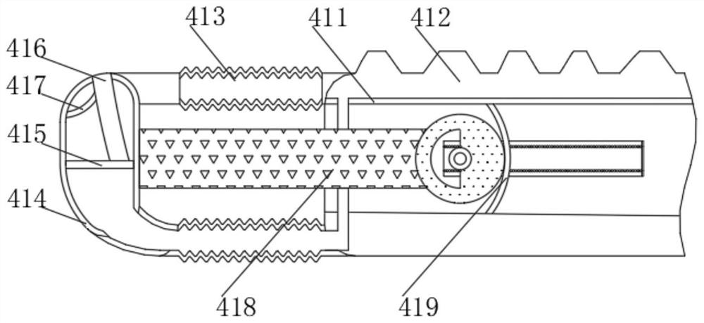
[0037] see Figure 2-4, the present invention provides a technical solution on the basis of Embodiment 1: a concrete pouring equipment, the feeding device 41 includes a connection and fixation shell 411, the top of the connection and fixation shell 411 is provided with a pressure air bag 412, and the connection and fixation shell The sides of 411 are fixedly connected with telescopic shell 413, and the end of telescopic shell 413 away from the fixed shell 411 is fixedly connected with retaining shell 414, and the inner side of retaining shell 414 is slidably connected with piston plate 415, one end of piston plate 415 The side is fixedly connected with a blocking plate 416, and the side of the blocking plate 416 away from the piston plate 415 runs through the material retaining housing 414, and one side of the blocking plate 416 is provided with a guiding and correcting support column 417, and the guiding and correcting supporting column 417 is far away from the side of the blo...
Embodiment 3
[0040] see Figure 3-6 , the present invention provides a technical solution on the basis of Embodiment 2: a concrete pouring equipment, the cleaning mechanism 186 includes a connecting seat 861, one end of the connecting seat 861 is fixedly connected with a mobile housing 862, and the bottom of the inner wall of the mobile housing 862 is fixed Connected with a pressure spring 863, the end of the pressure spring 863 away from the moving housing 862 is fixedly connected with a moving plate 864, and the side of the moving plate 864 away from the pressure spring 863 is fixedly connected with a moving rod 865. One end of the moving rod 865 away from the moving plate 864 is provided with Mounting slot 866. Mounting groove 866 inside is provided with swing clearing device 867, is all connected by driving connecting rod 185 rotations between connection seat 861, and cleaning mechanism 186 is provided with several, and swing clearing device 867 comprises clearing hole rod 671, and the...
PUM
 Abstract
Description
Claims
Application Information
 - R&D Engineer
- R&D Manager
- IP Professional
- Industry Leading Data Capabilities
- Powerful AI technology
- Patent DNA Extraction
Browse by: Latest US Patents, China's latest patents, Technical Efficacy Thesaurus, Application Domain, Technology Topic, Popular Technical Reports.
© 2024 PatSnap. All rights reserved.Legal|Privacy policy|Modern Slavery Act Transparency Statement|Sitemap|About US| Contact US: help@patsnap.com