Fuse and circuit system

A fuse and melt technology, applied in circuits, electrical components, emergency protection devices, etc., can solve problems such as a large number of arcs and poor safety performance

Active Publication Date: 2021-06-04
XIAN ZHONGRONG ELECTRIC CO LTD
View PDF9 Cites 2 Cited by
  • Summary
  • Abstract
  • Description
  • Claims
  • Application Information

AI Technical Summary

Problems solved by technology

However, when the fuse is disconnected by impact, it is easy to generate a large number of arcs, and the safety performance is poor.

Method used


Image

  • Fuse and circuit system
  • Fuse and circuit system
  • Fuse and circuit system

Examples


Embodiment 1

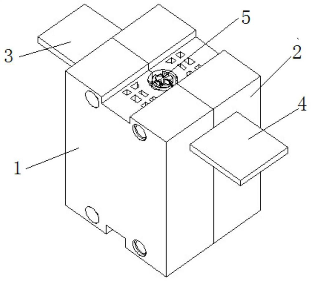
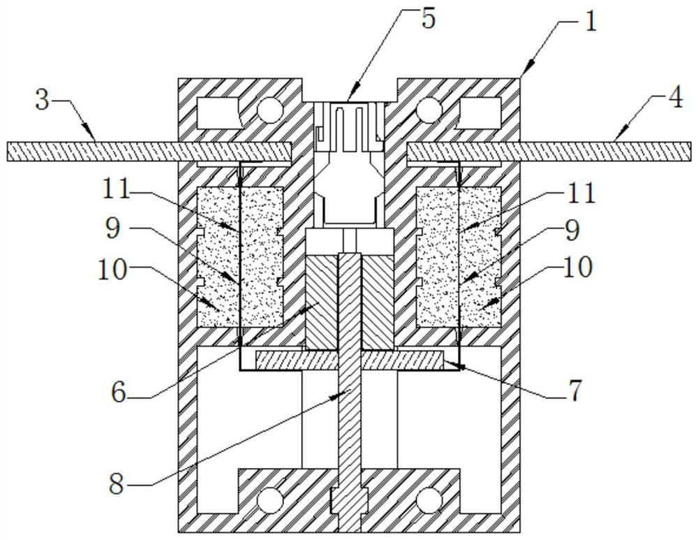
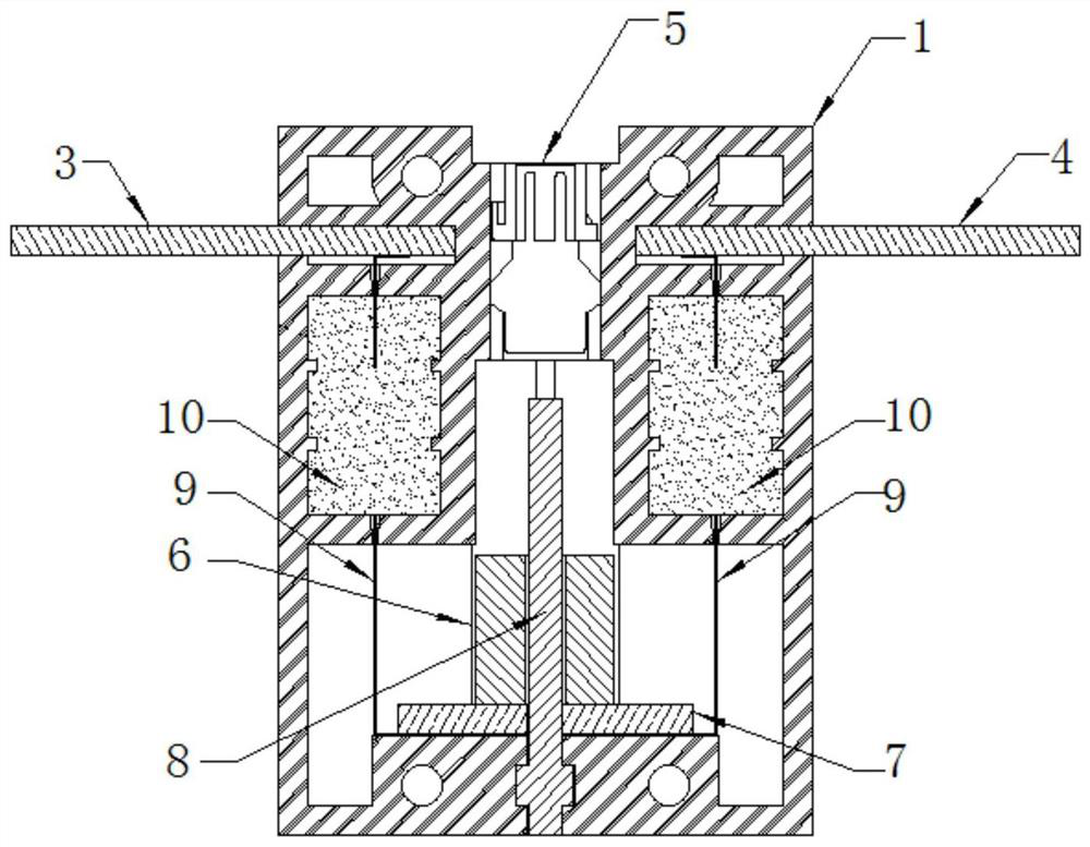
[0069] see figure 1 , figure 2 and image 3 , the housing is composed of the first sub-housing 1 and the second sub-housing 2 arranged on the left and right in an airtight combination. Partial accommodating cavities for accommodating the first conductive terminal 3 and the second conductive terminal 4 are respectively opened on the upper parts of the first sub-housing 1 and the second sub-housing 2 . After the first sub-housing 1 and the second sub-housing 2 are assembled, the first conductive terminal 3 and the second conductive terminal 4 are inserted into the accommodating cavity and are located on opposite sides of the housing at intervals. The combined housing can be fixed by screws.

[0070] A first cavity is opened in the casing between the first conductive terminal 3 and the second conductive terminal 4 , and a second cavity communicating with the first cavity is opened in the casing below the first cavity. The first cavity and the second cavity can be divided int...

Embodiment 2

[0080] see Figure 4 , Figure 5 , Figure 6 and Figure 7 , in this embodiment, the fuse housing is composed of a first sub-housing 21 and a second sub-housing 22 arranged up and down, the first conductive terminal 27 is inserted into the first sub-housing 21 located on the upper part, The two conductive terminals 23 are inserted into the lower second sub-housing 22 . Moreover, the first conductive terminal 27 and the second conductive terminal 23 include opposite parts at intervals, and the disconnection part 232 is disposed on a part of the second conductive terminal 23 opposite to the first conductive terminal 27 . Wherein, the disconnection portion 232 can be obtained by setting a weak point 231 on the second conductive terminal 23, and the weak point 231 can be a perforation or a disconnection groove extending along the width direction of the second conductive terminal 23 at both ends of the disconnection portion 232 and other structures. The shape of the breaking g...

Embodiment 3

[0097] as attached Figure 8As shown, the first conductive terminal 41 and the second conductive terminal 42 are arranged opposite to each other on the left and right sides of the upper part of the housing 43 . The upper part of the housing 43 is provided with two spaced and opposite closed chambers 46 , and the two closed chambers 46 are respectively located at the lower part of the first conductive terminal 41 and the second conductive terminal 42 . The closed chamber 46 on the left side is provided with the first melt 48 disconnected earlier and the first melt 47 disconnected later, and the closed chamber 46 on the right is provided with the first melt 48 disconnected earlier. Two melts and a second melt after disconnection.

[0098] The cavity at the bottom of the housing 43 is provided with a connecting conductive terminal 52, the upper end of the first disconnected first melt 48 and the later disconnected first melt 47 are connected to the first conductive terminal 41, ...


PUM


Abstract

The embodiment of the invention provides a fuse and a circuit system, and relates to the technical field of circuit protection. The fuse comprises a shell, a melt and an impact device, wherein the shell is internally provided with a closed chamber, the closed chamber is filled with an arc extinguishing filler, and the shell is connected with a first conductive terminal and a second conductive terminal which are respectively used as a current input end and a current output end; the melt is connected in series between the first conductive terminal and the second conductive terminal, and at least a part of the melt is arranged in the closed cavity in a penetrating manner; and the impact device is arranged in the shell, located outside the closed chamber and used for acting on the melt to generate an impact force when receiving an excitation signal so that the melt can be disconnected in the closed chamber. The fuse provided by the embodiment of the invention can be not limited by a fusing current, and can realize rapid cutting under different currents or even a zero current. A melt breaking position is in an arc extinguishing filler environment, sparks, electric arcs and the like cannot be leaked, and safety is high. In addition, the arc extinguishing filler and the impact device play a role without interfering with each other, and the stability is high.

Description

technical field [0001] The present application relates to the technical field of circuit protection, in particular, to a fuse and a circuit system. Background technique [0002] Fuses are a common circuit overcurrent protection product. Generally, a fuse of a fuse is blown by heat generated by the current when an excessive current flows through it. The load matching relationship of this kind of thermal fuse is difficult to determine. If a fuse with a low current specification cannot meet the short-time overshoot of the current, a fuse with a high current specification cannot meet the requirements for fast protection. [0003] Based on the above, the prior art provides a fuse with mechanical impact disconnection, which includes: a housing surrounded by a housing to form an installation cavity; a fuse piece, the fuse piece is arranged in the installation cavity; When external force acts, the fuse will be cut off. Cut off the fuse link by external force. However, when the f...

Claims


Application Information

Patent Timeline
Patent Type & Authority Applications(China)
IPC IPC(8): H01H85/38H01H85/143H01H85/18H01H85/36
CPCH01H85/38H01H85/143H01H85/18H01H85/36H01H39/006H01H2039/008H01H9/10H01H85/0241H01H85/10H01H85/12H01H3/22H01H3/24H01H9/34H01H85/0039
Inventor 石晓光戈西斌王伟曹辉王宁
Owner XIAN ZHONGRONG ELECTRIC CO LTD
Why Eureka
Try Eureka