Broadband circularly polarized metasurface antenna

A metasurface, circularly polarized technology, applied in the direction of antenna, antenna grounding device, antenna grounding switch structure connection, etc., can solve the problems of narrow bandwidth and unstable pattern, and achieve stable in-band pattern and good application value. Effect

Pending Publication Date: 2021-06-04
GUANGXI UNIVERSITY OF TECHNOLOGY
View PDF6 Cites 2 Cited by
  • Summary
  • Abstract
  • Description
  • Claims
  • Application Information

AI Technical Summary

Problems solved by technology

[0005] The technical problem to be solved by the present invention is the

Method used


Image

  • Broadband circularly polarized metasurface antenna
  • Broadband circularly polarized metasurface antenna
  • Broadband circularly polarized metasurface antenna

Examples


Example Embodiment

[0033] Example 1

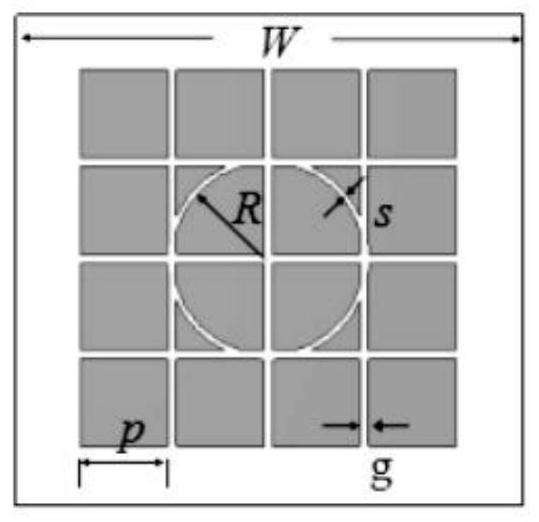
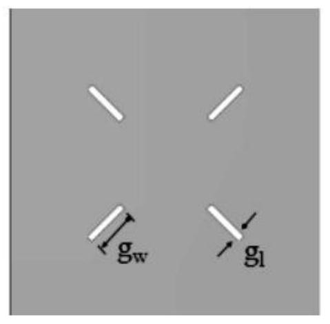
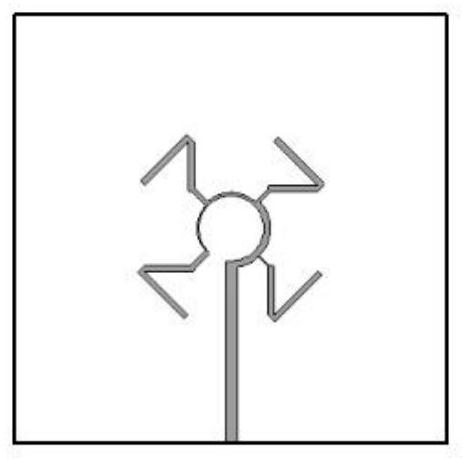
[0034] This embodiment provides a broadband circularly ultra-surface antenna, such as figure 1 , figure 2 , image 3 The broadband circularly polarized hyperbolite antenna includes: the two-layer dielectric plate and three metal layers, the same two-layer dielectric plate specifications; the three-layer metal layers are superioplasses of the top layer, the opening slotting floor of the intermediate layer and the most The underlying feed structure; the super surface is 4 × 4 metal square patch, and there is a circular groove for forming an annular current to generate a circularly polarized radiation; the slotting floor of the intermediate layer is provided for signal coupling. The same rectangle grooves in the same size.

[0035] Specifically, the bottom layer of feed structure is the sequential spiral feed structure.

[0036] Specifically, the dielectric plate is a F4B plate, a dielectric constant of 4.4 of the F4B plate, and is 0.001.

[0037] Specifically, the ...


PUM


Abstract

The invention relates to a broadband circularly polarized metasurface antenna, which solves the technical problems of unstable directional diagram and narrow bandwidth. Two layers of dielectric plates and three metal layers are adopted, wherein the two layers of dielectric plates have the same specification; the three metal layers are a super-surface patch at the top layer, a slotted floor at the middle layer and a feed structure at the bottommost layer respectively; a metasurface is a 4 * 4 metal square patch, and an annular groove used for forming annular current to generate circularly polarized radiation is formed in the metasurface; and the middle metal floor is provided with four rectangular grooves with the same size for signal coupling, so that the problem is well solved, and the circularly polarized antenna can be applied to a broadband circularly polarized antenna with a stable directional diagram.

Description

technical field [0001] The invention relates to the field of radio frequency antennas, in particular to a broadband circularly polarized metasurface antenna with stable pattern. Background technique [0002] In a wireless communication system, the antenna is an essential part, which can complete the transmission and reception of electromagnetic wave signals. Among them, the microstrip patch antenna has developed rapidly due to its small size, easy commonality, and easy manufacturing. The pattern characteristic is an important indicator of the microstrip patch antenna, and the quality of the pattern directly affects the working frequency band of the antenna. In many cases, it is the distortion of the antenna pattern that limits the bandwidth of the antenna and its application in engineering. There are many factors that affect the antenna pattern, such as the size of the finite floor, the coupling between patches, the influence of higher order modes, etc. To improve the ant...

Claims


Application Information

Patent Timeline
IPC IPC(8): H01Q1/38H01Q1/48H01Q1/50H01Q15/24H01Q15/00
CPCH01Q1/38H01Q1/48H01Q1/50H01Q15/24H01Q15/0086Y02D30/70
Inventor 高喜田国伟许恩永王国富陈华金曾伟光李思敏谢先明
Owner GUANGXI UNIVERSITY OF TECHNOLOGY
Why Eureka
Try Eureka