One charging control method, device and system

A charging control method and charging control technology, applied in the field of electronics, can solve the problems of reducing the failure rate of BMS, poor voltage follow-up of charging modules, etc., and achieve the effects of improving charging efficiency, fast voltage regulation, and reducing the rate of change

Active Publication Date: 2022-08-09
CHONGQING XINYUANCHUANG IND CO LTD
View PDF8 Cites 0 Cited by
  • Summary
  • Abstract
  • Description
  • Claims
  • Application Information

AI Technical Summary

Problems solved by technology

[0004] Aiming at the deficiencies in the prior art, the present invention provides a charging control method, device and system, which solves the problem of poor voltage followability of the charging module in the prior art charging control method for batteries, thereby reducing the The rate of change of the charging current per unit time reduces the impact on the BMS, prolongs the battery life, and reduces electromagnetic interference emissions, reducing the BMS failure rate

Method used


Image

  • One charging control method, device and system
  • One charging control method, device and system
  • One charging control method, device and system

Examples


Embodiment 1

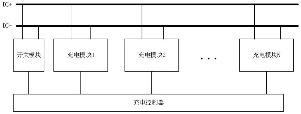
[0030] figure 2 Shown is a schematic structural diagram of a charging control system provided by an embodiment of the present invention, such as figure 2 As shown, the charging control system provided by this embodiment specifically includes:

[0031] A charging controller, a switch module and several charging modules;

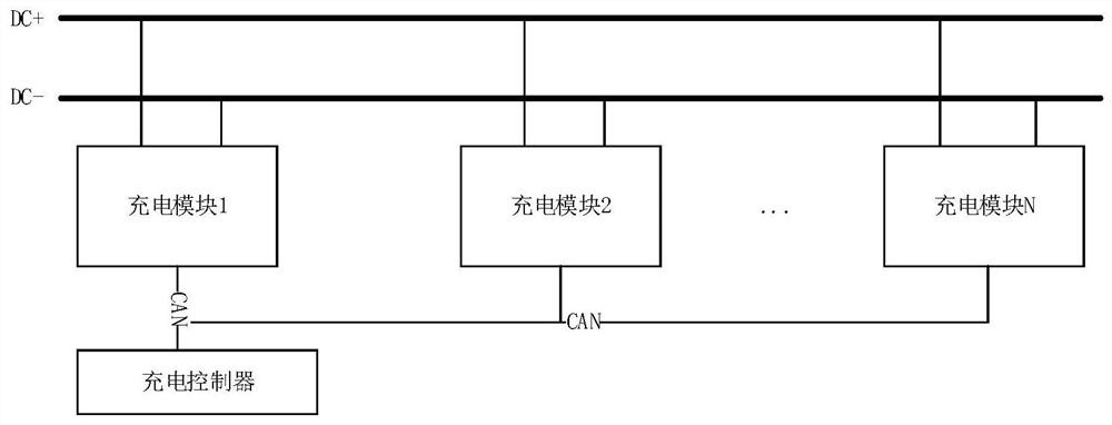
[0032] The input ends of the plurality of charging modules are connected to an external AC power source when in use, and the output ends of the plurality of charging modules are connected in parallel to the DC bus for converting the external AC power source into a target DC power source for charging an external battery;

[0033] The charging controller is connected in communication with the plurality of charging modules and the switch module, and is also connected with an external battery management system when in use, and is used for the target voltage and each battery according to the target voltage sent by the external battery management system. The uni...

Embodiment 2

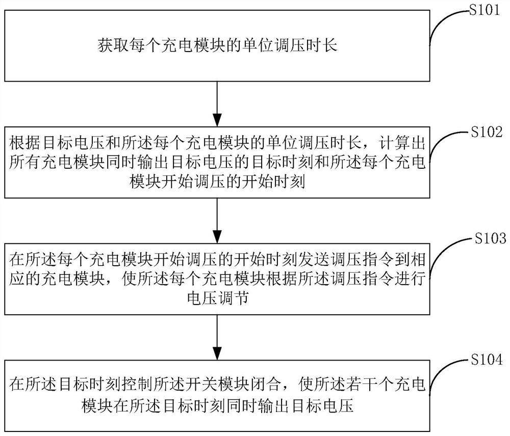
[0039] image 3 Shown is a schematic flowchart of a charging control method provided by an embodiment of the present invention, such as image 3 As shown, the charging control method provided in this embodiment is applied to a charging controller of a charging control system, and the charging control system further includes a switch module and several charging modules, and specifically includes the following steps:

[0040] Step S101, obtaining the unit voltage regulation duration of each charging module;

[0041] Further, as Figure 4 As shown, in step S101, the unit voltage regulation time length of each charging module is obtained, which specifically includes:

[0042] Step S201, controlling the current charging module to output an initial voltage;

[0043] Step S202, sending a test command to the current charging module and recording the first moment of sending the test command, so that the current charging module performs voltage regulation according to the test voltag...


PUM


Abstract

The present invention provides a charging control method, device and system. The control method includes: obtaining the unit voltage regulation time of each charging module; The module simultaneously outputs the target time of the target voltage and the start time when each charging module starts voltage regulation; at the start time when each charging module starts voltage regulation, a voltage regulation command is sent to the corresponding charging module, so that each charging module starts voltage regulation. The charging module performs voltage regulation according to the voltage regulation instruction; at the target time, the switch module is controlled to close, so that the several charging modules simultaneously output the target voltage at the target time; The new charging control method has the problem of poor voltage follow-up of the charging module, thereby reducing the rate of change of the charging current per unit time, reducing the impact on the BMS, prolonging the battery life, reducing electromagnetic interference emissions, and reducing the BMS failure rate.

Description

technical field [0001] The present invention relates to the field of electronic technology, and in particular, to a charging control method, device and system. Background technique [0002] The core component of the charging pile is the charging module, and its stable operation has become a key factor restricting the service life of the charging pile; in order to provide more power to the car battery in a unit time, the electric vehicle charging pile needs to output a large current. However, the charging current is large, and due to the constraints of volume and heat dissipation, a single charging module cannot provide such a large current. At present, multiple charging modules are usually connected in parallel on the market, that is, each charging module is connected in parallel to the DC bus to increase the output current. When the charging controller receives the voltage command sent by the battery management system (BMS), the charging controller directly Send voltage re...

Claims


Application Information

Patent Timeline
Patent Type & Authority Patents(China)
IPC IPC(8): H02J7/00H02J7/02H02J7/04B60L53/00B60L53/60
CPCH02J7/00712H02J7/007188H02J7/02H02J7/04H02J7/0029B60L53/00B60L53/60Y02T90/14
Inventor 严冬罗剑峰
Owner CHONGQING XINYUANCHUANG IND CO LTD
Why Eureka
Try Eureka