Electric transformer dynamic combined voltage regulating on-load voltage regulating method and apparatus

A technology of power transformer and voltage regulating winding, applied in the direction of transformer/inductor coil/winding/connection, etc., can solve the problems of affecting parallel operation, power grid overvoltage shock, complex structure, etc., to reduce the closing excitation inrush current, reduce the resistance Pressure requirements, the effect of simple control methods

Active Publication Date: 2007-04-04
WUHAN UNIV
View PDF2 Cites 0 Cited by
  • Summary
  • Abstract
  • Description
  • Claims
  • Application Information

AI Technical Summary

Problems solved by technology

Since the closing or opening time of the mechanical switch is much longer than the change period of the voltage, coupled with the dispersion of the mechanical action, the transition process of the voltage and current inevitably occurs during the tap switching process, and an arc is generated, thus causing the insulation oil pole Decomposition, damage to switch contacts, and sometimes even burnout of transformers, causing large-scale power outages
The following problems exist in the operation of the traditional transformer mechanical switch on-load voltage regulating device: (1) The adjustment time of the mechanical tap cannot be accurately controlled, and the overvoltage impact on the power grid is inevitable; (2) The mechanical tap is prone to failure, resulting in wrong Gears or dislocations, causing serious power outage accidents (three such accidents occurred in a power supply bureau within one year); (3) Arcs generated between mechanical contacts polarized the transformer insulating oil, and often needed to replace and filter the insulating oil, resulting in a large maintenance workload ; (4) Fast, dynamic, and frequent adjustments cannot be made; (5) Cutting off no-load transformers produces high overvoltage; (6) Transformers operating in parallel cannot be regulated synchronously, therefore, affecting parallel operation
One is a hybrid type: the non-contact power electronic device works with a contact switch, it only solves the problem (3), and other problems are not really solved; the other is an alternative type: the traditional transformer voltage regulating winding The structure remains unchanged, and the tap switch is directly replaced by a power electronic switch. It has a complex structure, uses a large number of expensive power electronic devices, and is expensive.

Method used


Image

  • Electric transformer dynamic combined voltage regulating on-load voltage regulating method and apparatus
  • Electric transformer dynamic combined voltage regulating on-load voltage regulating method and apparatus

Examples


Embodiment Construction

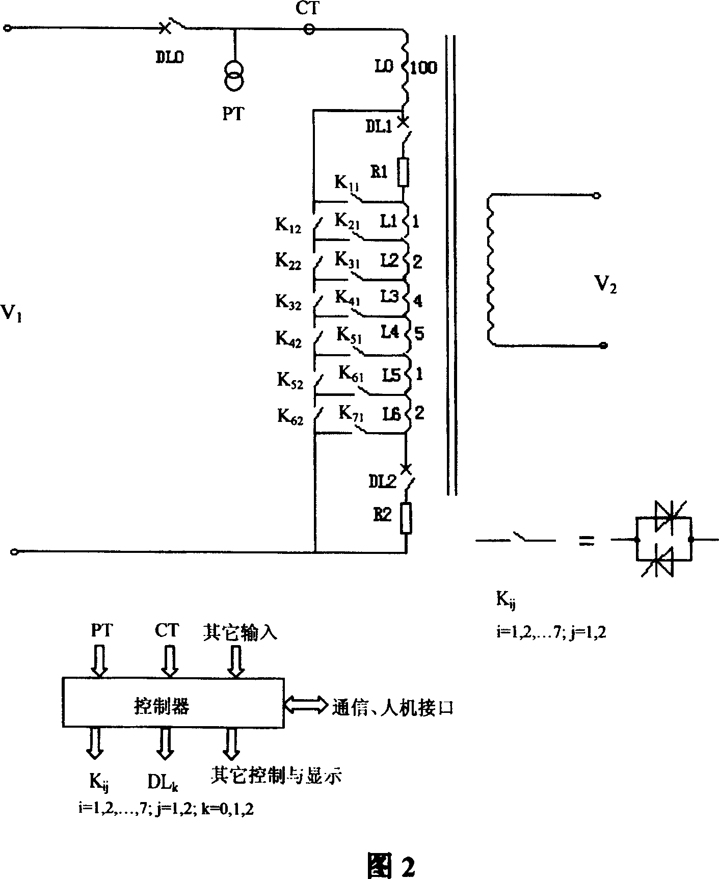
[0030] The working principle of the present invention will be further introduced in conjunction with accompanying drawing 2 below. Take the 15% voltage regulation range as an example.

[0031] In accompanying drawing 2, PT and CT represent voltage transformer and current transformer respectively. DL0, DL1, and DL2 represent the main circuit breaker and two auxiliary circuit breakers respectively. R1 and R2 represent current limiting resistors respectively. L1, L2, L3, L4, L5 and L6 represent six voltage regulating windings respectively. K11, K21, K31, K41, K51, K61 and K71 respectively represent 7 arm power electronic switches. K12, K22, K32, K42, K52 and K62 represent 6 bridge power electronic switches respectively.

[0032] The bridge arm type voltage regulating unit of the present invention can be represented by the voltage regulating winding L1 and K11, K21 and K12, or by the voltage regulating winding L2 and K21, K31 and K22.

[0033] The maximum number of voltage re...


PUM


Abstract

The transformer is voltage regulated in the primary with winding comprising one main winding and several serially connected voltage regulating windings in the same winding direction. The bridge voltage regulating unit comprises one voltage regulating winding, electronic power switches in two arms and one bridge electronic power switch. The voltage regulating windings have unequal capacity. When the voltage regulating value is M%, the serially connected voltage regulating winding number is less than M-1. The present invention has simple structure, less electronic power switches used, small size, low cost and high reliability.

Description

technical field [0001] The invention belongs to the technical field of on-load voltage regulation of power system transformers, in particular to a method and device for on-load voltage regulation of dynamic combined windings of power transformers. Background technique [0002] At present, the traditional transformer on-load voltage regulating device is commonly used in domestic and foreign power systems for voltage regulation, and its principle is shown in Figure 1. The device connects or disconnects certain voltage regulating windings through mechanical tap switches, changes the transformation ratio of the transformer, and limits the current of the windings through current limiting resistors or reactors, and prevents winding open circuits through auxiliary moving contact switching. , to prevent the short circuit damage or disconnection of the corresponding winding during the switching process of the tap to cause a power outage, so as to realize the on-load voltage regulatio...

Claims


Application Information

Patent Timeline
Patent Type & Authority Patents(China)
IPC IPC(8): H01F27/28
Inventor 李晓明尹项根
Owner WUHAN UNIV
Why Eureka
Try Eureka