Interlayer signal transmission structure of microwave mixed printed circuit board

A transmission structure and signal layer technology, applied in the microwave field, can solve the problem of large standing wave coefficient of cross-layer transmission of microwave mixed plate signals

Inactive Publication Date: 2014-10-08
CNGC INST NO 206 OF CHINA ARMS IND GRP
View PDF3 Cites 7 Cited by
  • Summary
  • Abstract
  • Description
  • Claims
  • Application Information

AI Technical Summary

Problems solved by technology

[0006] In order to avoid the deficiencies of the prior art, the present invention proposes a microwave mixed plate signal layer-to-layer transmission structure, which uses theoret

Method used


Image

  • Interlayer signal transmission structure of microwave mixed printed circuit board
  • Interlayer signal transmission structure of microwave mixed printed circuit board
  • Interlayer signal transmission structure of microwave mixed printed circuit board

Examples


specific Embodiment

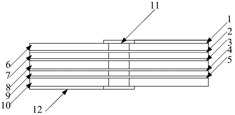
[0030] The printed circuit board design adopts the microwave mixed pressure multi-layer printed board process. Cascade structure such as figure 1 shown. This embodiment is a 6-layer board, 1 is the top signal transmission line (top layer), 2 is the top signal ground layer (second layer), 3 is the control layer (third layer), 4 is the power layer (fourth layer), 5 12 is the bottom signal transmission line (the sixth layer). The substrate used is: the material used for the first substrate 6 is Rogers4350B, and its dielectric constant ε r1 =3.66; the material used for the second substrate 7, the third substrate 8, the fourth substrate 9 and the fifth substrate 10 is TU662, and its dielectric constant ε r2 = 3.8.

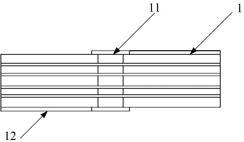
[0031] Such as Figure 5 , 6 shown. 11 is a through hole connecting the top layer and the bottom layer, and 13 is three ground holes for building a coaxial structure, and the ground holes run through the top layer to the bottom layer. 1 is a signal transmission ...


PUM


Abstract

The invention relates to an interlayer signal transmission structure of a microwave mixed printed circuit board. The interlayer signal transmission structure comprises a top-layer signal transmission line, a through hole for connecting a top layer with a bottom layer and a bottom-layer signal transmission line. The interlayer signal transmission structure is characterized in that two or more grounding holes are formed in any positions, except the position of a microstrip line, on the circumference of the through hole to form a coaxial structure, and the impedance of the coaxial structure is equal to the impedance of a system; the grounding holes penetrate through the top layer and the bottom layer. According to the technical scheme and the design idea, on the condition of ensuring signal transmission quality, the interlayer signal transmission structure greatly improves the integration level of the system, solves the problems which radio frequency engineers can not solve for so long, and has wide application prospect.

Description

technical field [0001] The invention belongs to the field of microwave technology, and relates to a signal interlayer transmission structure of a microwave mixed pressure board, which is specifically applied in S-band multi-channel transceiver components. Background technique [0002] With the rapid development of modern radar systems, many new requirements have been put forward in the field of microwave technology. For example, the manufacture of microwave printed boards is not only satisfied with the production of single and double boards, but the demand for microwave multilayer printed boards has become More and more urgent, thus the microwave mixed laminate production technology was born. The birth of the microwave mixed pressure board will inevitably bring about various new problems, among which the cross-layer signal transmission of the microwave mixed pressure board is an important issue. The existing literature materials do not make a clear analysis and research on ...

Claims


Application Information

Patent Timeline
IPC IPC(8): H05K1/11H01P3/00
Inventor 赵宇博王栋荀民刘洪升刘俊李建玲姚玮宋强党亚丽王鹏
Owner CNGC INST NO 206 OF CHINA ARMS IND GRP
Why Eureka
Try Eureka