

Driving method for liquid flow of micro-fluidic chip
A technology of microfluidic chips and driving methods, applied in fluid controllers, chemical instruments and methods, and laboratory containers, etc., can solve difficult and unrealistic problems in mass production, achieve rapid mass production, and reduce production difficulty Effect
- Summary
- Abstract
- Description
- Claims
- Application Information
AI Technical Summary
Problems solved by technology
Method used
Image

Examples
Embodiment Construction
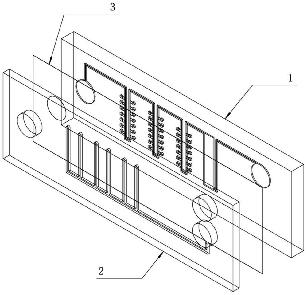
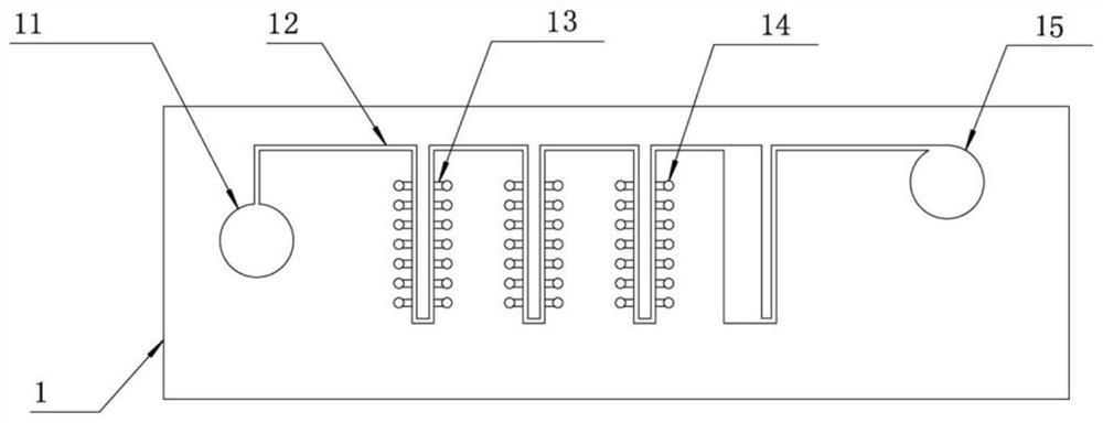
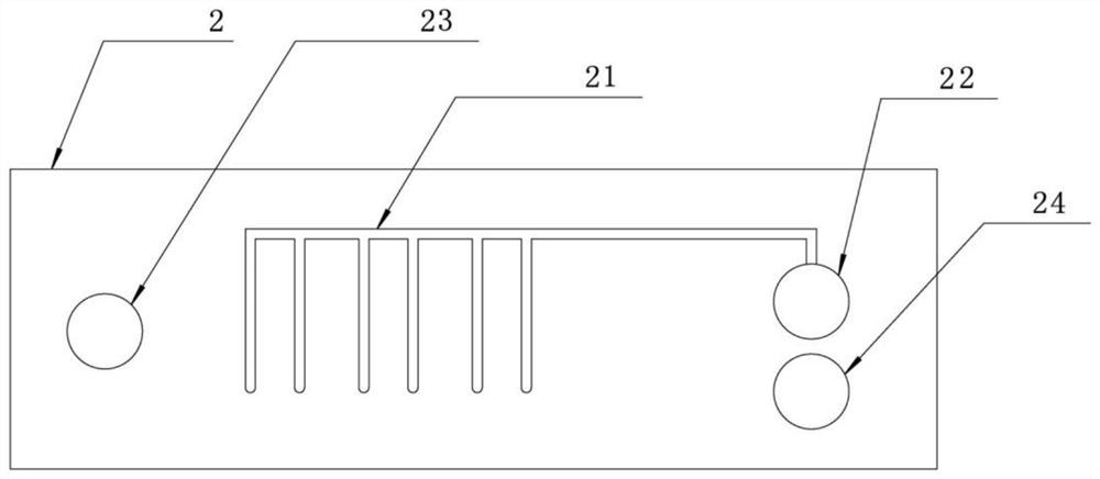
[0026] Such as Figure 1 to Figure 4 As shown, in a microfluidic chip for detection in the embodiment, the liquid flows from the liquid inlet 11 through the main channel 12 to the outlet 15 at the end of the main channel. In order to make the channel branch 13 and the branch well 14 is filled with liquid, the main channel 12 and flow channel branch 13 of the main chip 1 are open, covered by the isolation film 3, the entire main chip 1 is a closed chip, except for the escape port In addition, since the isolation membrane 3 is air-permeable and impermeable, the isolation membrane 3 is above the main channel 12, the flow channel branch 13 and the branch well 14, so the liquid is also sealed in the main chip 1. Above, the negative pressure channel 21 on the upper plate 2 communicates with the area of the isolation membrane 3 above the branch wells 14, so that after the liquid enters the channel branch 13, it will The pressure makes the inspection fluid in the main channel 12 fi...
PUM
 Abstract
Description
Claims
Application Information