Mold closing forming process and device for composite material

A composite material and molding device technology, applied in the field of composite material closed mold molding equipment, can solve the problems of inconvenient operation, inconvenient continuous operation, unfavorable processing output, etc., and achieve the effect of convenient installation and convenient closed mold molding process

Active Publication Date: 2021-06-08
江苏恒运兴达新材料科技有限责任公司
View PDF6 Cites 0 Cited by
  • Summary
  • Abstract
  • Description
  • Claims
  • Application Information

AI Technical Summary

Problems solved by technology

[0005] There is a phenomenon that it is not convenient for continuous operation, it is not conducive to centralized production operations, and it will cause certain inconvenience in operation. At the same time, it is not convenient for the production of integral molding of the inner end, which is not conducive to integrated processing and output, and needs to be improved.

Method used


Image

  • Mold closing forming process and device for composite material
  • Mold closing forming process and device for composite material
  • Mold closing forming process and device for composite material

Examples


Embodiment 1

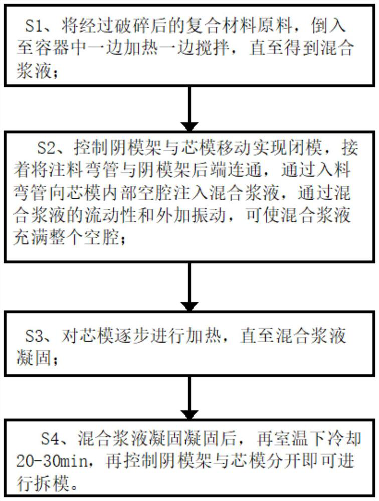
[0051] A closed-mold molding process for composite materials, such as figure 1 shown, including the following steps:

[0052] S1. Pour the crushed composite material raw materials into a container while heating and stirring until a mixed slurry is obtained;

[0053] S2. Control the movement of the female mold frame and the core mold to close the mold, then connect the injection elbow with the rear end of the female mold frame, and inject the mixed slurry into the inner cavity of the core mold through the feeding elbow, through the fluidity of the mixed slurry. With external vibration, the mixed slurry can fill the entire cavity;

[0054] S3, gradually heating the mandrel until the mixed slurry is solidified.

[0055] S4. After the mixed slurry is solidified and solidified, cool it at room temperature for 30 minutes, and then control the female mold frame and the mandrel to separate to remove the mold.

[0056] Preferably, the composite material raw materials in the step S1 ...

Embodiment 2

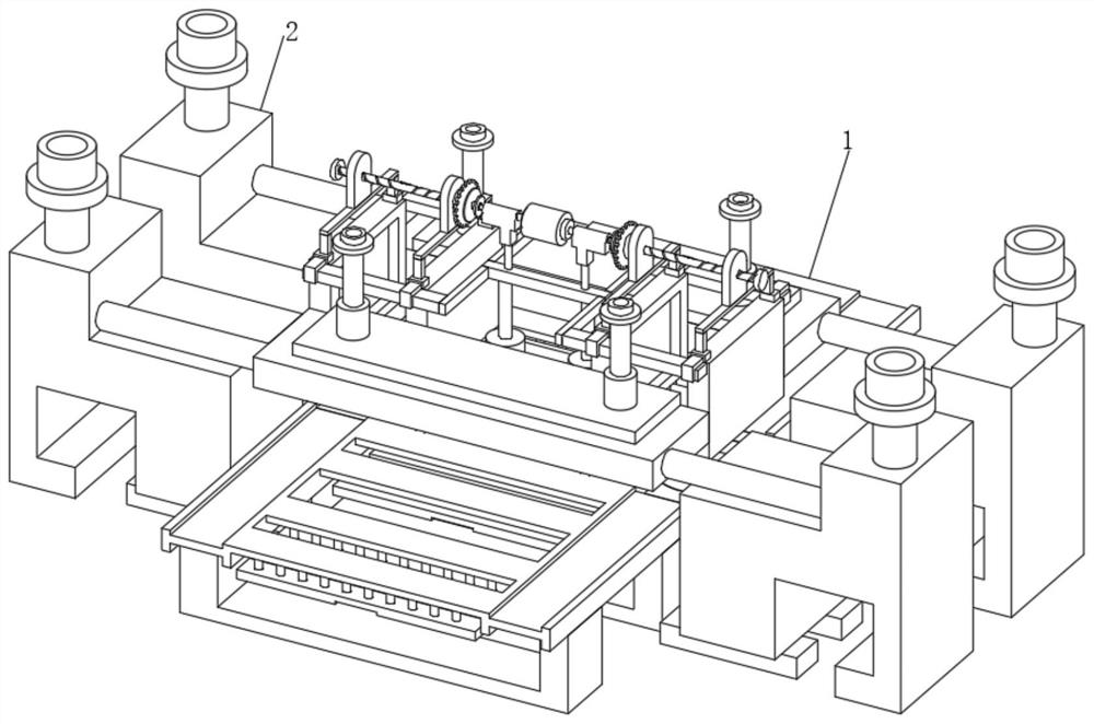
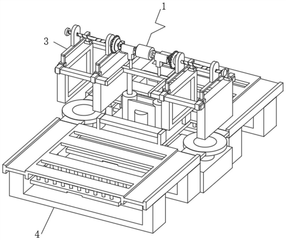
[0070] On the basis of Example 1, such as Figure 11 As shown, the mold closing device 1 also includes a top plate cover 35, a column support plate 36, a heating rod 37 and an installation bracket 38. The column support plate 36 is located at the side end position of the buffer barrel frame 33, and the upper end position of the column support plate 36 is in contact with the mounting bracket. The bracket 38 is fixedly connected, the upper end of the mounting bracket 38 is fixedly connected to the top plate cover 35 , and the heating rod 37 is electrically connected to the bottom of the mounting bracket 38 .

[0071] When this embodiment is in use, the user can electrically connect with the outside world through the heating rod 37, and the top plate cover 35 and the mounting bracket 38 help to install the heating rod 37 to realize the installation of the heating rod 37, and the installation of the mounting bracket 38 The bottom end is fixedly connected with the side end of the b...


PUM


Abstract

The invention discloses a mold closing forming process and device for a composite material. The device comprises a mold closing device, a material injection device is fixedly connected to the side end position of the mold closing device, the mold closing device comprises a closing assembly and a conduction assembly, the conduction assembly is arranged at the bottom of the inner end of the mold closing device, and the upper end position of the center of the conduction assembly is fixedly connected with the closing assembly. The closing assembly comprises a working end, hydraulic telescopic devices and a supporting end, the hydraulic telescopic devices are symmetrically connected to the two sides of the bottom of the inner end of the closing assembly, the working end is arranged at the upper ends of the hydraulic telescopic devices, the lower end of the center of the working end is fixedly connected with the supporting end, and the working end comprises a closing connecting module and a displacement module. The displacement module is arranged at the top of the inner end of the working end, and the closing connecting module is in threaded connection with the lower end of the displacement module. According to the mold closing forming process and device for the composite material, the purpose of inner end mold closing is achieved through the arrangement of the mold closing device.

Description

technical field [0001] The invention relates to the technical field of closed-mold forming equipment for composite materials, in particular to a process and device for closed-mold forming of composite materials. Background technique [0002] According to Chinese Patent No. CN102581921B, the present invention discloses a pneumatic pouring mold opening and closing device, the structure of which includes a plurality of interacting mold opening and closing units; Mold; the mold includes an outer mold skeleton and an inner template; the top of the mold is provided with a translation mechanism, and the translation mechanism includes a cantilever beam track, a pulley and a pulley seat, one end of the cantilever beam track is fixed on the fixed frame, and the pulley is fixed through the pulley seat on the top of the mould; the pulley is slidingly matched with the cantilever beam track; the cylinder body of the driving cylinder is fixed on the fixed frame, and the piston rod of the d...

Claims


Application Information

Patent Timeline
IPC IPC(8): B29C45/12B29C45/66B29C45/46B29C45/73C08L63/00C08K13/04C08K7/06C08K5/1515C08K5/05
CPCB29C45/12B29C45/66B29C45/46B29C45/73C08K13/04C08K7/06C08K5/1515C08K5/05B29C2045/665C08L63/00
Inventor 刘汝斌刘超杨士超
Owner 江苏恒运兴达新材料科技有限责任公司
Why Eureka
Try Eureka