Unmanned aerial vehicle water forced landing transportation device

A technology for transportation devices and UAVs, which is applied in the field of UAV ditching transportation devices, and can solve problems such as damage to UAVs, loss, and uncontrollability

Pending Publication Date: 2021-06-08
童友福
View PDF4 Cites 0 Cited by
  • Summary
  • Abstract
  • Description
  • Claims
  • Application Information

AI Technical Summary

Problems solved by technology

[0003] UAVs are prone to various problems during flight so that they have to make forced landings. In the prior art, there are many researches on forced landings of unmanned aerial vehicles, such as CN108313314A / CN206984391U, but the above-mentioned forced landing devices can only play a role on land or in the field. Among them, forced landing on the water surface is a major problem in UAV forced landing technology. The patent document with the Chinese patent application number 202010731854.2 discloses a UAV water forced landing transportation device. The invention can move and adjust the position on the water surface by itself, thereby Improve the accuracy of the UAV when it is forced to land, prevent the UAV from falling into the water when it is forced to land, and can also fix the main body when the UAV is forced to land, preventing the water flow from changing the position of the main body so that the UAV cannot be forced to land normally, and The inflatable bag can be popped up at the bottom of the main body to increase the load and prevent the drone from being pressed into the water due to the weight of the drone after the drone is forced to land, which will cause damage to the drone.
However, the UAV is easy to lose control when it is forced to land, and the area of ​​the transport device of this patent cannot be adjusted, which will cause the UAV to fall into the water, damage the UAV, and cause losses. An airbag is installed under the drone, but the support of the airbag on the water is prone to uncertain shaking and uncontrollable

Method used


Image

  • Unmanned aerial vehicle water forced landing transportation device
  • Unmanned aerial vehicle water forced landing transportation device
  • Unmanned aerial vehicle water forced landing transportation device

Examples


Embodiment Construction

[0025] In describing the present invention, it should be understood that the terms "center", "longitudinal", "transverse", "length", "width", "thickness", "upper", "lower", "front", " Orientation indicated by rear, left, right, vertical, horizontal, top, bottom, inside, outside, clockwise, counterclockwise, etc. The positional relationship is based on the orientation or positional relationship shown in the drawings, and is only for the convenience of describing the present invention and simplifying the description, rather than indicating or implying that the referred device or element must have a specific orientation, be constructed and operated in a specific orientation, Therefore, it should not be construed as limiting the invention.

[0026] In the description of the present invention, "plurality" means two or more, unless otherwise specifically defined.

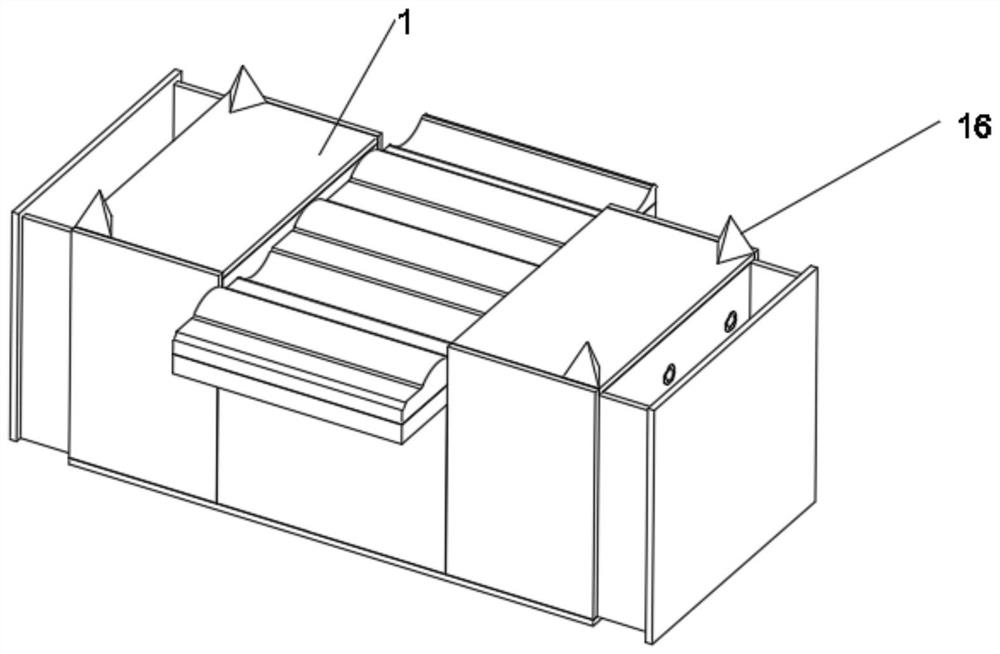
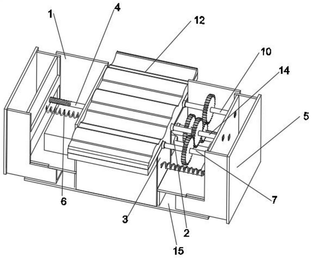
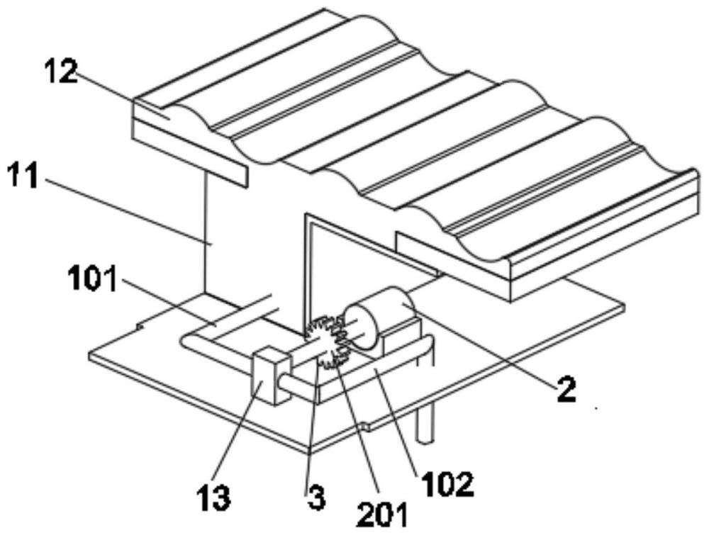
[0027] see Figure 1-5 , the present invention provides a kind of technical scheme:

[0028] An unmanned aerial vehi...


PUM


Abstract

The invention discloses an unmanned aerial vehicle water forced landing transportation device, and belongs to the technical field of unmanned aerial vehicle forced landing. The unmanned aerial vehicle forced landing transportation device comprises a shell, a motor is arranged in the shell, an output shaft of the motor is connected with a water pumping mechanism, a screw rod is arranged above the water pumping mechanism, the thread turning directions of the left end and the right end of the screw rod are opposite, the two ends of the screw rod are in threaded connection with push boxes, and the push boxes and the shell are fixedly connected with springs. A transmission shaft A is arranged in front of the screw rod, the left side of the transmission shaft A is sleeved with a front cover plate, the rear side of the front cover plate abuts against a rear cover plate, and the rear cover plate is connected with a transmission shaft B through sleeving. Front and rear cover plates can be overturned through gear transmission, the landing area of the device is enlarged, and the unmanned aerial vehicle is prevented from being out of control and falling into water due to difficulty in landing to the center of the transportation device. By arranging a water bag, the water bag is used for buffering impact force generated when the unmanned aerial vehicle lands, and the unmanned aerial vehicle is prevented from being damaged by the impact force.

Description

technical field [0001] The invention relates to the technical field of UAV forced landing, and more specifically, relates to a UAV water forced landing transportation device. Background technique [0002] UAVs are unmanned aircraft operated by radio-controlled equipment and self-contained program controls, or operated entirely or intermittently autonomously by an on-board computer. At present, it has applications in aerial photography, agriculture, plant protection, micro selfie, express transportation, disaster relief, observing wild animals, monitoring infectious diseases, surveying and mapping, news reporting, power inspection, disaster relief, film and television shooting, creating romance and so on. [0003] UAVs are prone to various problems during flight so that they have to make forced landings. In the prior art, there are many researches on forced landings of unmanned aerial vehicles, such as CN108313314A / CN206984391U, but the above-mentioned forced landing devices ...

Claims


Application Information

Patent Timeline
Patent Type & Authority Applications(China)
IPC IPC(8): B63B35/52
CPCB63B35/52B64U70/00
Inventor 童友福
Owner 童友福
Why Eureka
Try Eureka