Pilot middle cavity balance pressure-type ultrahigh pressure ball valve for oil and gas production equipment

A technology for oil and gas extraction and ultra-high pressure, applied in mechanical equipment, valve devices, cocks including cut-off devices, etc.

Pending Publication Date: 2021-06-08
SUZHOU DOUSON VALVE CO LTD
View PDF0 Cites 0 Cited by
  • Summary
  • Abstract
  • Description
  • Claims
  • Application Information

AI Technical Summary

Problems solved by technology

In the field of high-pressure equipment, the valve ball will be subjected to the high pressure generated by the fluid. The pressure bearing capacity of the existing ball valve is generally below 70MPa. The design ratio of the ball will cause the opening stroke of the pressure relief section to be too long. Due to the structural characteristics of the ball valve, when the opening stroke of the valve ball is extended, when the valve seat is opened for pressure relief at the end, the sealing surface of the valve seat partially contacts the valve ball. Further cause a sudden increase in torque, resulting in difficulty in opening or partial damage to the sealing surface

Method used


Image

  • Pilot middle cavity balance pressure-type ultrahigh pressure ball valve for oil and gas production equipment
  • Pilot middle cavity balance pressure-type ultrahigh pressure ball valve for oil and gas production equipment
  • Pilot middle cavity balance pressure-type ultrahigh pressure ball valve for oil and gas production equipment

Examples


Embodiment 1

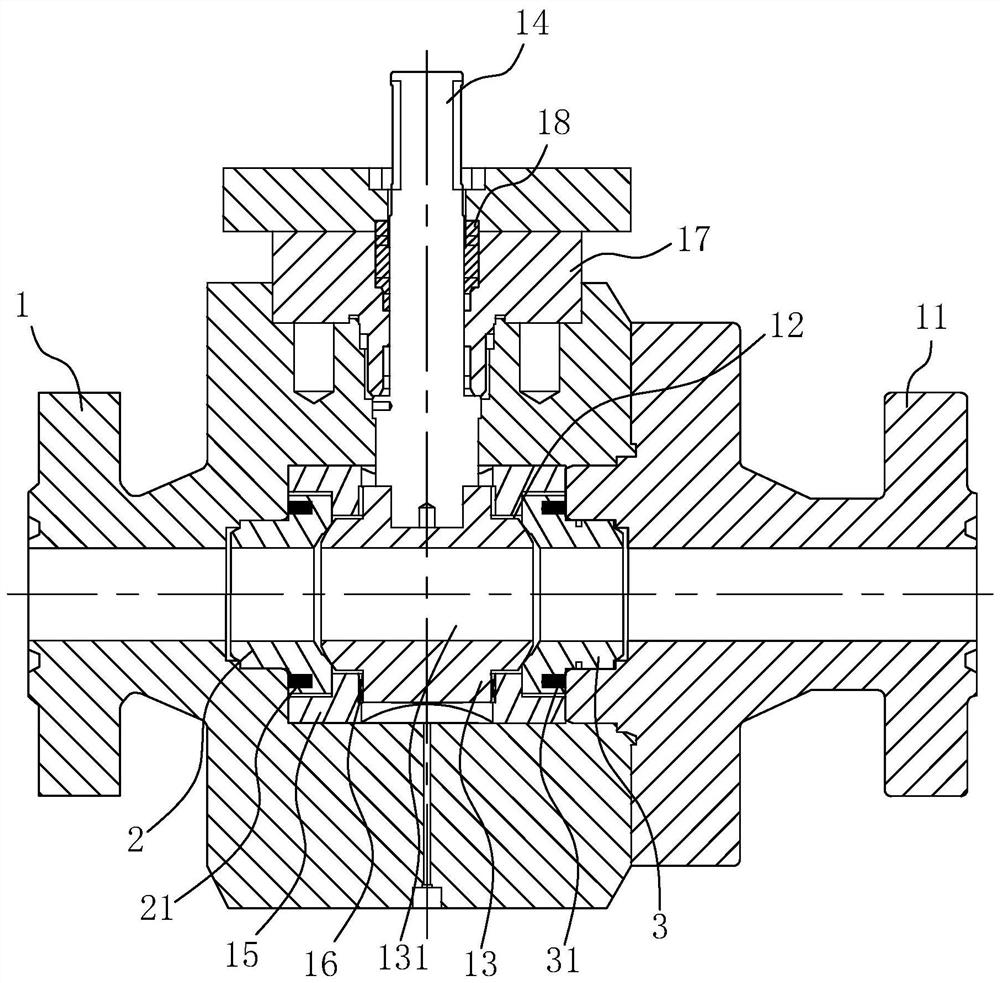
[0039] A kind of oil and gas production equipment with a pilot cavity balance pressure type ultra-high pressure ball valve, such as Figure 1 to Figure 3 As shown, it includes: a main valve body 1, an auxiliary valve body 11 is provided on one side of the main valve body 1, an installation chamber 12 is provided in the main valve body 1, and a valve ball 13 is rotatably connected to the installation chamber 12, and the valve ball The middle part of 13 is provided with a diversion channel 131, and the main valve body 1 is rotatably connected with a valve stem 14 fixed to the valve ball 13; and the second sealing valve seat 3, the first sealing valve seat 2 and the second sealing valve seat 3 are sealed and fitted, and the first sealing valve seat 2 and the second sealing valve seat 3 are provided with valve balls 13 for sealing On the contact sealing surface, a first sealing elastic member 21 is provided between the first sealing valve seat 2 and the main valve body 1, and a se...

Embodiment 2

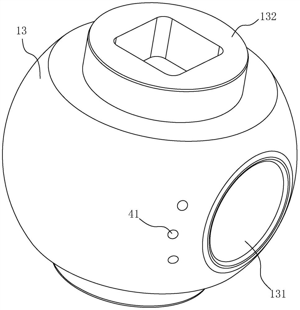
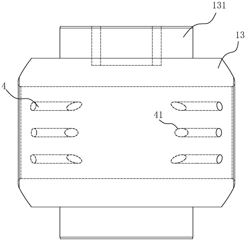
[0045] The difference between this embodiment and other embodiments is that in this embodiment: Figure 4 and Figure 5 As shown, the pressure relief structure 4 includes: a diversion hole 42 communicated with the installation chamber 12, and a number of pressure relief holes 41 arranged on one side of the diversion channel 131, the pressure relief hole 41 communicates with the diversion hole 42, In addition, in this embodiment, two sets of pressure relief holes 41 and diversion flow holes 42 are arranged in a centrally symmetrical manner, and each set of pressure relief holes 41 is provided with three sets, and the diversion channel 131 runs through the upper and lower ends of the valve ball 13; The pressure hole 41 guides the high-pressure medium into the guide flow hole 42 , and then the flow guide channel 131 releases the high pressure into the installation chamber 12 , thereby forming a pressure balance.

Embodiment 3

[0047] The difference between this embodiment and other embodiments is that in this embodiment: Figure 6 As shown, the pressure relief structure 4 includes: a guide hole 42 communicating with the installation chamber 12, and a number of pressure relief holes 41 arranged on one side of the flow guide channel 131. The pressure relief hole 41 is connected with the guide flow hole 42 and the flow guide The channel 131 is connected at the same time, and in this embodiment, two sets of pressure relief holes 41 and guide flow holes 42 are arranged in a centrally symmetrical manner, and each set of pressure relief holes 41 is provided with three sets, and the flow guide channel 131 runs through the upper and lower sides of the valve ball 13 Both ends; through the mutual cooperation of the pressure relief hole 41 and the guide flow hole 42, the high-pressure medium is introduced into the installation chamber 12 and the introduction channel at the same time, making the pressure balance ...


PUM


Abstract

The invention relates to a pilot middle cavity balance pressure-type ultrahigh pressure ball valve for oil and gas production equipment. The pilot middle cavity balance pressure-type ultrahigh pressure ball valve comprises a main valve body, a first sealing valve seat, a second sealing valve seat and a pressure relief structure, wherein an auxiliary valve body is arranged at one side of the main valve body; a mounting cavity is formed in the main valve body; a valve ball is rotationally connected to the interior of the mounting cavity; a flow guide channel is formed in the middle of the valve ball; the first sealing valve seat and the second sealing valve seat are movably connected to the main valve body and oppositely arranged at two sides of the valve ball; and the pressure relief structure is arranged on the valve ball and is used for guiding a high-pressure medium to the mounting cavity to form a pressure balance state after the valve ball rotates to be opened at a preset angle. Due to the arrangement of the pressure relief structure, when the valve ball is rotated until the pressure relief structure corresponds to the flow guide channel, the high-pressure medium firstly enters the pressure relief structure to communicate with the mounting cavity, and at the moment, the pressure between the mounting cavity and the auxiliary valve body is balanced, so that quick opening and quick pressure relief are realized, the opening torque is reduced, the pressure relief stroke is shortened, damage to the sealing surface in the opening process is reduced, and the service life of the ball valve is prolonged.

Description

technical field [0001] The invention relates to the technical field of valves, in particular to a pilot middle-cavity pressure-balanced ultra-high pressure ball valve for oil and gas exploitation equipment. Background technique [0002] The valve is a control component in the pipeline fluid conveying system, which is used to change the passage section and the flow direction of the medium, and has the functions of diversion, cut-off, throttling, check, diversion or overflow and pressure relief. Ball valve is one of the most widely used valves. Its opening and closing part is a valve ball. The valve ball is driven by the valve stem and rotates around the axis of the valve stem to realize the opening and closing action. In the field of high-pressure equipment, the valve ball will be subjected to the high pressure generated by the fluid. The pressure bearing capacity of the existing ball valve is generally below 70MPa. The design ratio of the ball will cause the opening stroke ...

Claims


Application Information

Patent Timeline
Patent Type & Authority Applications(China)
IPC IPC(8): F16K5/06F16K5/20
CPCF16K5/06F16K5/0605F16K5/0663F16K5/201
Inventor 邓金先李树林陈林黄辉
Owner SUZHOU DOUSON VALVE CO LTD
Why Eureka
Try Eureka