Eureka AIR delivers breakthrough ideas for toughest innovation challenges, trusted by R&D personnel around the world.

Scannable system and scanning method thereof

A technology of a scanning system and a scanning method, which is applied in the field of wearable devices for monitoring hematocrit, can solve problems such as affecting the hematocrit value, difficult to effectively eliminate background signals, and large data gaps, so as to improve self-learning and accuracy The effect of sex and convenience

Pending Publication Date: 2021-06-08
上海浩创亘永科技有限公司
View PDF8 Cites 0 Cited by
  • Summary
  • Abstract
  • Description
  • Claims
  • Application Information

AI Technical Summary

Problems solved by technology

[0004] However, in the prior art, when the optical detection device is used to extract the signal, due to the movement of the measurement part, natural light, fluorescent lamp and other interference, the finally measured signal needs to be filtered by many methods
And because the human body is an extremely complex living body that changes with time, there is usually a big difference between the body data of the previous second and the body data of the next few seconds, and due to heavy physical work, the red blood cells may increase, which affects the red blood cell ratio. Capacitance value, so the data gap between static, working and after working is larger, it is difficult to effectively eliminate the background signal

Method used


Image

  • Scannable system and scanning method thereof
  • Scannable system and scanning method thereof
  • Scannable system and scanning method thereof

Examples


Embodiment 1

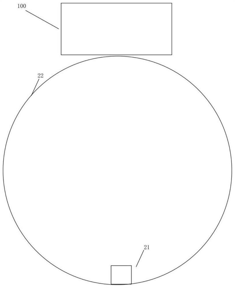
[0042] figure 1 In order to include the wearable device 22 of the body abnormality monitoring scanning system 100, the wearable device can be a bracelet worn on the wrist; the wearable device can also be a finger ring worn on the finger. The scanning system 100 for monitoring body abnormalities is located outside the wearable device 22 , and the third light source receiver 21 is located opposite to the scanning system 100 for monitoring body abnormalities and is arranged inside the wearable device.

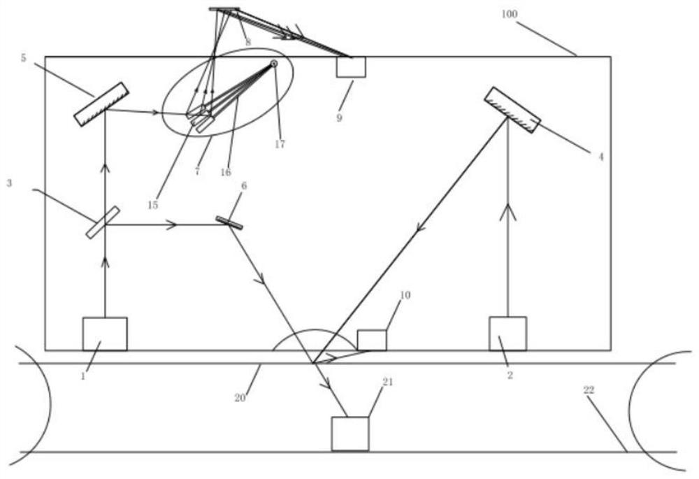
[0043] A scanning system is a system that can test the hematocrit value while realizing barcode scanning. Such as figure 2 As shown, the scanning system 100 includes a first optical emission system 1 and a second optical emission system 2 with different wavelengths, and the light emitted by the first optical emission system 1 is divided into a vertical first beam and a second beam after passing through a spectroscopic system The light emitted by the second optical emission syst...

Embodiment 2

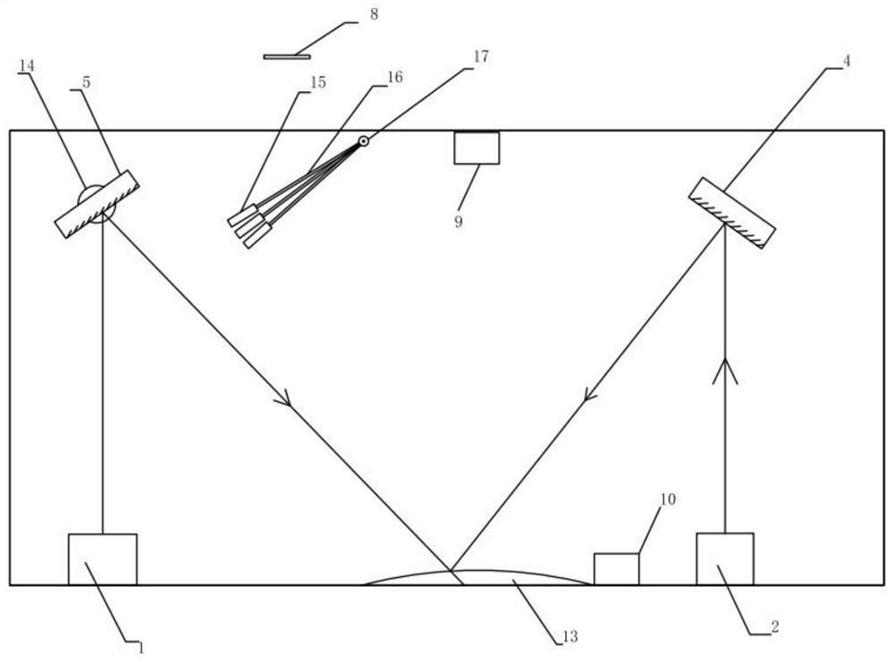
[0069] Such as Figure 3-4 As shown, a scanning system is a system that can test red blood cells while realizing two-dimensional code scanning. The scanning system includes a first optical emission system 1 and a second optical emission system 2 with different wavelengths; a third mirror 5 is arranged on the first swing mechanism 14 to form a second swing reflection module, and the angle of the third reflector 5 can be adjusted through the swing range of the first swing mechanism 14 .

[0070] In mode one, when testing the barcode gap, the second swing reflection module adjusts the angle of the third reflector 5, so that the light emitted by the first optical emission system 1 is reflected by the third reflector 5 as a second beam, and the second optical The light emitted by the emission system 2 is reflected by the second reflector 4 to generate a third light beam, the light of the second light beam directly merges with the third light beam, and irradiates the skin from the w...


PUM


Abstract

The invention relates to a scannable system and a scanning method thereof, which can be used for identifying different states including a static state, a working state and a post-working state and processing data so as to obtain relatively accurate data, and identifying different lesions in different states in combination with an established model. The system can continuously verify and optimize the model, can realize autonomous learning and updating, and improves the accuracy and reliability of lesion identification.

Description

technical field [0001] The invention relates to the wearable field, in particular to a wearable device for monitoring hematocrit. Background technique [0002] In recent years, with the rapid development of sensor technology, flexible wearable devices and other sciences, the use of scanning systems to check goods in warehouses has been widely popularized. However, the existing scanning systems can only scan barcodes and cannot monitor people wearing the scanners in real time. The physical condition of the staff is abnormal, and the code scanning work in the warehouse either often maintains a movement to scan the code, or may carry out heavy handling work. When the body is unwell, it cannot be self-discovered in time, which will inevitably lead to safety hazards. The hematocrit refers to the percentage of red blood cells in the whole blood volume. It reflects the ratio of red blood cells to plasma and is the main factor affecting blood viscosity. Therefore, the hematocrit va...

Claims


Application Information

Patent Timeline
Patent Type & Authority Applications(China)
IPC IPC(8): G01N33/49G06K9/62
CPCG01N33/49G06F18/241
Inventor 杨心怀舒洁芸王志特
Owner 上海浩创亘永科技有限公司
Why Eureka
Eureka Blog
Learn More