Mismatch loss calculation method and device, equipment and storage medium

A calculation method and area technology, applied in the field of solar energy, can solve problems such as backside mismatch loss, uneven distribution, uneven distribution on the backside of modules, etc.

Pending Publication Date: 2021-06-08
TRINASOLAR CO LTD
View PDF6 Cites 0 Cited by
  • Summary
  • Abstract
  • Description
  • Claims
  • Application Information

AI Technical Summary

Problems solved by technology

The radiation reception on the back of the bifacial power generation module is affected by the installation conditions, such as the installation height, the distance between the front and rear rows, the installation inclination and the reflectivity of the ground scene. The viewing angle coefficients are different, and the radiation on the back of the bifacial module is unevenly distributed. Under the non-ideal state, the radiation inhomogeneity on the back of the bifacial module is affected by the shading of supports (such as brackets, cement piers), etc., which will aggravate the uneven distribution on the back of the module. , which further expands the mismatch loss on the back of the bifacial module
[0003] In the case of traditional photovoltaic modules for power generation, backside power generation also needs to be considered, but due to installation conditions, the backside radiation of double-sided modules is unevenly distributed, causing mismatch losses
In the prior art, when calculating the mismatch loss of bifacial power generation modules, only the loss of the overall photovoltaic module is considered, and the backside mismatch loss caused by the installation conditions of the bifacial modules is not considered separately, or only the bifacial group loss in the ideal installation state is considered. Matching loss, does not consider the mismatch loss caused by obstructions such as brackets

Method used


Image

  • Mismatch loss calculation method and device, equipment and storage medium
  • Mismatch loss calculation method and device, equipment and storage medium
  • Mismatch loss calculation method and device, equipment and storage medium

Examples


Embodiment 1

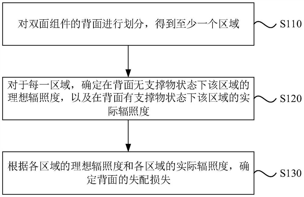
[0029] Figure 1A It is a flow chart of a mismatch loss calculation method provided in Embodiment 1 of the present application; this embodiment is applicable to the calculation of mismatch loss on the back of a bifacial module, especially for the back of a bifacial module under the condition of a support The case of the mismatch loss calculation. The method can be executed by a mismatch loss calculation device, which is implemented by software / hardware, and can be integrated into an electronic device carrying a mismatch loss calculation function, such as a server.

[0030] Such as Figure 1A The method shown, the method specifically includes:

[0031] S110. Divide the backside of the bifacial module to obtain at least one area.

[0032] Among them, the so-called bifacial module is a module that can realize power generation on the front and back sides, such as solar modules. Optionally, the double-sided component includes a direct side and a back side. The direct side means ...

Embodiment 2

[0082] Figure 2A It is a flow chart of a mismatch loss calculation method provided in Embodiment 2 of the present application; on the basis of the above embodiment, for "for each region, determine the ideal irradiance of the region in the state of no support on the back , and the actual irradiance of this area in the state of the support on the back” to elaborate, such as Figure 2A The method shown, the method may specifically include:

[0083] S210. Divide the backside of the bifacial component to obtain at least one area.

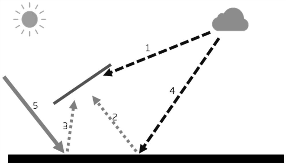
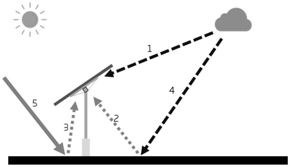
[0084] S220. For each area, determine the ideal irradiance of the area in the state of no support on the back according to the ground scattered reflection irradiance, the ground direct reflection irradiance and the air scattering irradiance of the area.

[0085] In this embodiment, for each area, according to the ground scattered reflection irradiance, ground direct reflection irradiance and air scattering irradiance of the area, determine the ideal i...

Embodiment 3

[0142] image 3 It is a schematic structural diagram of a mismatch loss calculation device provided in Embodiment 3 of the present application; this embodiment is applicable to the calculation of the mismatch loss on the back of a bifacial module, especially for the back of a bifacial module under the condition of a support The case of the mismatch loss calculation. The device is implemented by software / hardware, and can be integrated into an electronic device carrying a mismatch loss calculation function, such as a server.

[0143] Such as image 3 As shown in the device, the device includes an area determination module 310, an irradiance determination module 320 and a mismatch loss determination module 330, wherein,

[0144] The area determination module 310 is configured to divide the back of the bifacial component to obtain at least one area; wherein, the back of the bifacial component is the side of the bifacial component facing away from the light source;

[0145] The...


PUM


Abstract

The invention discloses a mismatch loss calculation method and device, equipment and a storage medium. The back surface of the double-sided assembly is divided to obtain at least one area; the back face of the double-face assembly is the face, back to a light source, of the double-face assembly. For each area, the ideal irradiance of the area in the state that the back face is not provided with the support and the actual irradiance of the area in the state that the back face is provided with the support are determined; and the mismatch loss of the back surface is determined according to the ideal irradiance of each region and the actual irradiance of each region. According to the technical scheme, a new thought is provided for calculation of the mismatch loss of the back face of the double-face assembly, and meanwhile support is provided for design of a related system for subsequently improving the generating capacity by evaluating the shielding influence of the supporting object on the double-face assembly.

Description

technical field [0001] The embodiments of the present application relate to the technical field of solar energy, and in particular to a mismatch loss calculation method, device, equipment, and storage medium. Background technique [0002] Different from conventional single-sided photovoltaic modules, bifacial modules can be a type of solar module that can realize power generation on both sides. The radiation reception on the back of the bifacial power generation module is affected by the installation conditions, such as the installation height, the distance between the front and rear rows, the installation inclination and the reflectivity of the ground scene. The viewing angle coefficients are different, and the radiation on the back of the bifacial module is unevenly distributed. Under the non-ideal state, the radiation inhomogeneity on the back of the bifacial module is affected by the shading of supports (such as brackets, cement piers), etc., which will aggravate the une...

Claims


Application Information

Patent Timeline
IPC IPC(8): G06F30/20
CPCG06F30/20
Inventor 孙凯吴军全鹏黄国昆印杰赵明
Owner TRINASOLAR CO LTD
Why Eureka
Try Eureka