A Design Method of Multipath Power Distribution/Combiner
A design method and synthesizer technology, applied to circuits, waveguide devices, connection devices, etc., can solve problems such as long simulation optimization time, difficulty in adding design and optimization, and difficulty in power distribution/combination, so as to save design and optimize time, reducing the effect of optimized parameters
- Summary
- Abstract
- Description
- Claims
- Application Information
AI Technical Summary
Problems solved by technology
Method used
Image
Examples
Embodiment 1
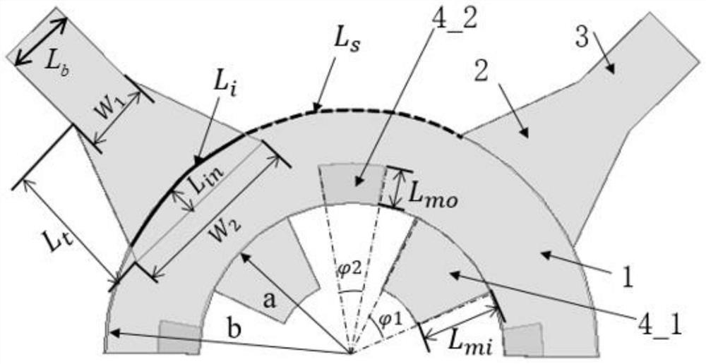
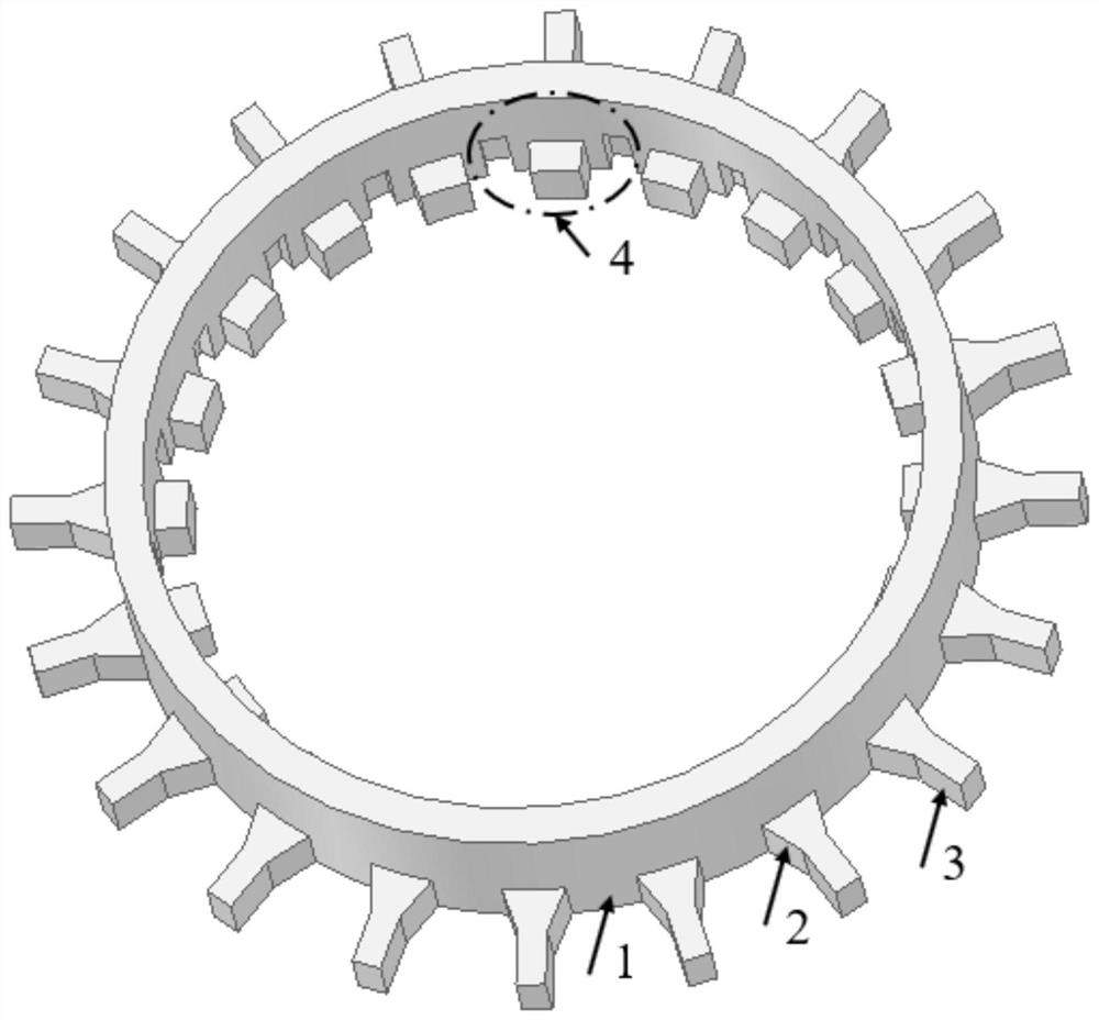
[0026] Set N=20, calculate according to step 1 to obtain the outer radius of the coaxial waveguide (1) b=51.46mm; according to step 2, take b-a=0.55λ=4.7mm, calculate and obtain the inner radius of the coaxial waveguide (1) a=46.76mm ;According to step 3, the size of the matching structure is calculated as follows: the fan-shaped slot (4_1) corresponds to the central angle Thickness L mi =4mm, the fan-shaped block (4_2) corresponds to the central angle L mo =0.5L mi =2mm; according to step 4, the model of the standard rectangular waveguide is BJ320 (7.112mm×3.556mm); according to step 5, the size of the straight trapezoidal transition waveguide structure (2) is: W 1 =3.556mm, W 2 =8.65mm, L t =7mm,L in = 1.5mm; Simulation modeling is carried out according to the device structure size calculated by the above steps, and the structure diagram is as follows figure 2 As shown, the lengths of the standard rectangular waveguide and the coaxial waveguide are both greater tha...
Embodiment 2
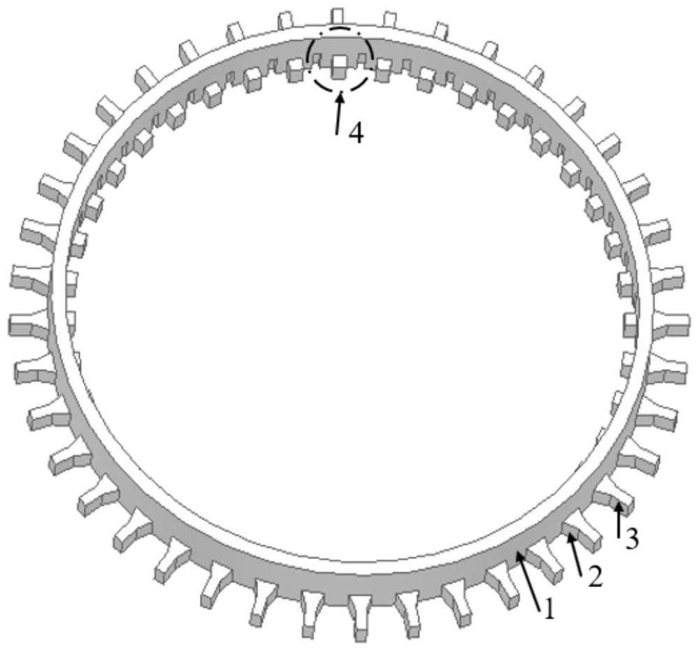
[0028] N=40 is set, and all the other steps are the same as in Embodiment 1. The dimensions of the device calculated through the design steps are respectively: b=99.57mm, a=94.87mm, L mo =0.5L mi = 2mm, W 1 =3.556mm, W 2 =8.65mm, L t =7mm,L in =1.5mm, the standard rectangular waveguide is BJ320 (7.112mm×3.556mm), and the waveguide length is 20mm. Through simulation modeling, it is obtained as image 3 In the structure shown, the lengths of the standard rectangular waveguide and the coaxial waveguide are both 20 mm. The S-parameters of this structure are calculated by simulation as Figure 5As shown, the insertion loss of the device at 35GHz is 0.11dB, and the insertion loss in the 34.51GHz-35.68GHz frequency band is less than 0.2dB.
PUM
 Abstract
Description
Claims
Application Information
 - R&D
- Intellectual Property
- Life Sciences
- Materials
- Tech Scout
- Unparalleled Data Quality
- Higher Quality Content
- 60% Fewer Hallucinations
Browse by: Latest US Patents, China's latest patents, Technical Efficacy Thesaurus, Application Domain, Technology Topic, Popular Technical Reports.
© 2025 PatSnap. All rights reserved.Legal|Privacy policy|Modern Slavery Act Transparency Statement|Sitemap|About US| Contact US: help@patsnap.com


