Power distribution cabinet with high heat dissipation performance

A high heat dissipation, power distribution cabinet technology, applied in substation/distribution device casings, electrical components, dispersed particle filtration, etc., can solve the problems of insufficient heat dissipation effect and power waste, save power, increase heat dissipation, and achieve high efficiency. cooling effect

Active Publication Date: 2021-06-08
深圳市森通电力科技有限公司
View PDF8 Cites 2 Cited by
  • Summary
  • Abstract
  • Description
  • Claims
  • Application Information

AI Technical Summary

Problems solved by technology

[0003] At present, the existing power distribution cabinets have heat dissipation mechanisms, such as heat dissipation holes, heat dissipation fans, etc., but there are certain disadvantages. For example, if the heat dissipation is only through the heat dissipation holes, the heat dissipation effect may be insufficient, but the heat dissipation through the fans, When the temperature drops, the fan is still working, and there will be a waste of electric energy; if the fan can be controlled according to the actual situation, the waste of electric energy will be greatly reduced, so we have designed a power distribution with high heat dissipation performance Cabinet to solve the above problems

Method used


Image

  • Power distribution cabinet with high heat dissipation performance
  • Power distribution cabinet with high heat dissipation performance
  • Power distribution cabinet with high heat dissipation performance

Examples


Embodiment Construction

[0025] The following will clearly and completely describe the technical solutions in the embodiments of the present invention with reference to the accompanying drawings in the embodiments of the present invention. Obviously, the described embodiments are only some, not all, embodiments of the present invention.

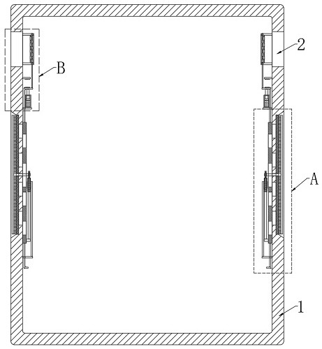
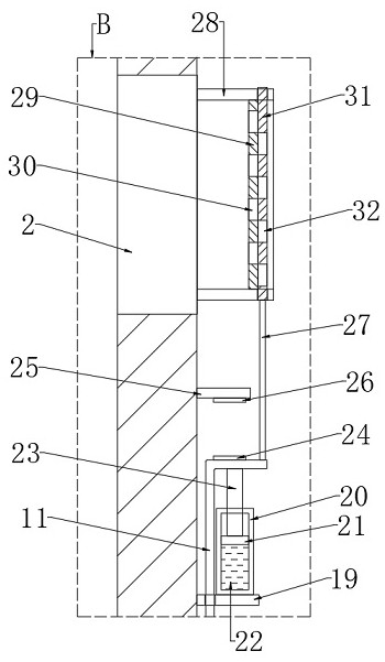
[0026] refer to Figure 1-4 , a power distribution cabinet with high heat dissipation performance, including a cabinet body 1, cooling fans 2 are installed on the upper ends of both sides of the cabinet body 1, and air inlet pipes 28 are installed on the air inlet ends of the two cooling fans 2, and the air inlet The pipe 28 is located inside the cabinet body 1, and the air inlet pipe 28 is connected with the air inlet end of the cooling fan 2 through bolts, wherein the air inlet pipe 28 is a rectangular pipe.

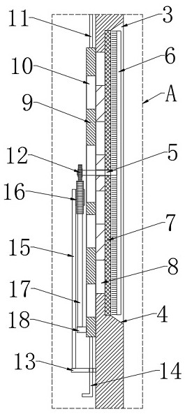
[0027] The cabinet body 1 is provided with a ventilation mechanism respectively located below the two heat dissipation fans 2. The ventilation mechanism incl...


PUM


Abstract

The invention discloses a power distribution cabinet with high heat dissipation performance, which comprises a cabinet body, wherein the upper ends of the two sides of the cabinet body are both provided with heat dissipation fans, the air inlet ends of the two heat dissipation fans are both provided with air inlet pipes, the cabinet body is provided with ventilation mechanisms which are respectively positioned below the two heat dissipation fans, and each ventilation mechanism comprises a first fixing block and a second fixing block which are fixed on the inner wall of the cabinet body, and each second fixing block is located above the corresponding first fixing block. According to the power distribution cabinet, the structure is reasonable, the size of a first through hole and a second through hole can be automatically adjusted according to the temperature, so that the air inlet amount in the cabinet body can be adjusted, the heat dissipation effect on the cabinet body can be improved, and meanwhile, along with the increase of the temperature, the heat dissipation fans can work, so that more effective and efficient heat dissipation can be carried out in the cabinet body, a dustproof net can be automatically cleaned, manual cleaning is not needed, and the labor amount of workers is reduced.

Description

technical field [0001] The invention relates to the technical field of power distribution cabinets, in particular to a power distribution cabinet with high heat dissipation performance. Background technique [0002] Power distribution cabinets (boxes) are divided into power distribution cabinets (boxes), lighting distribution cabinets (boxes), and metering cabinets (boxes), which are the final equipment of the power distribution system. The power distribution cabinet is a general term for the motor control center. The power distribution cabinet is used in the occasions where the load is relatively scattered and there are few circuits; the motor control center is used in the occasions where the load is concentrated and there are many circuits. They distribute the electric energy of a certain circuit of the upper-level power distribution equipment to the nearest load. This level of equipment shall provide protection, monitoring and control of the load. [0003] At present, ...

Claims


Application Information

Patent Timeline
Patent Type & Authority Applications(China)
IPC IPC(8): H02B1/56H02B1/30H02B1/28B01D46/00B01D46/10
CPCH02B1/565H02B1/30H02B1/306H02B1/28B01D46/10B01D46/681Y02A30/14
Inventor 奚占洲
Owner 深圳市森通电力科技有限公司
Why Eureka
Try Eureka