
Clock synchronization network, clock trigger network and real-time trigger processing method

A clock synchronization and clock technology, which is applied in time division multiplexing systems, electrical components, multiplexing communications, etc. Problems such as real-time interaction, synchronous timing and difficult expansion of network structure

Active Publication Date: 2021-06-08
合肥中科采象科技有限公司
View PDF5 Cites 1 Cited by
  • Summary
  • Abstract
  • Description
  • Claims
  • Application Information

AI Technical Summary

Problems solved by technology

At the same time, in experimental physics, it is often necessary to build a real-time trigger network to eliminate invalid cases and reduce the system data rate.
[0003] The existing clock synchronization network often has the following limitations: the tree topology network used in the prior art is unidirectional, which can only realize the distribution of synchronous clock and control information, and it is difficult to support the real-time interactive transmission and processing of trigger information
Additional construction of trigger network makes the system very complex
[0004] Therefore, in order to ensure the synchronization accuracy of data acquisition, the existing clock synchronization network is difficult to realize real-time interaction of multi-level trigger information, synchronous timing and technical problems that the network structure is difficult to expand.

Method used


Image

  • Clock synchronization network, clock trigger network and real-time trigger processing method
  • Clock synchronization network, clock trigger network and real-time trigger processing method
  • Clock synchronization network, clock trigger network and real-time trigger processing method

Examples


Embodiment Construction

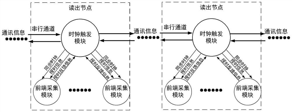
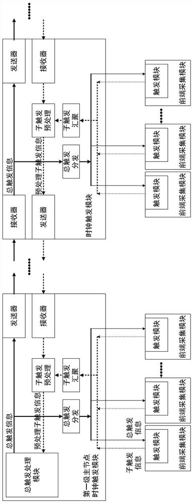
[0052] The present disclosure provides a clock synchronization network, including: N clock trigger modules, used to obtain and transmit communication information, and output synchronous clocks, wherein, each two clock trigger modules can transmit communication information to each other; N front-end The acquisition module group is set corresponding to each clock trigger module, and is used to receive the synchronous clock and communication information, acquire the collected data synchronously and in real time, and output sub-trigger information to the corresponding clock trigger module. The clock synchronization network in the present disclosure realizes synchronous timing, real-time control and trigger interaction among distributed nodes with only one transmission network, which greatly simplifies global timing and control system deployment.

[0053] In order to make the purpose, technical solutions and advantages of the present disclosure clearer, the present disclosure will b...


PUM


Abstract

The invention provides a clock synchronization network, a clock trigger network and a real-time trigger processing method. The clock synchronization network comprises N clock trigger modules which are used for obtaining and transmitting communication information and outputting a synchronous clock, wherein each two clock trigger modules can transmit the communication information to each other; N front-end acquisition module groups which are arranged corresponding to the clock trigger modules and are used for receiving the synchronous clock and the time service information, synchronously acquiring acquisition data in real time and outputting sub-trigger information to the corresponding clock trigger modules, wherein each front-end acquisition module group comprises at least one front-end acquisition module, and the front-end acquisition module is suitable for synchronously acquiring signal waveforms in real time and acquiring acquired data. According to the clock synchronization network disclosed by the invention, synchronous time service, real-time control and trigger interaction among distributed nodes can be realized by only using one transmission network, and global time service and control system deployment are greatly simplified.

Description

technical field [0001] The present disclosure relates to the field of clock synchronization control of experimental physics, in particular to a clock synchronization network, a clock trigger network and a real-time trigger processing method. Background technique [0002] In order to ensure the synchronization accuracy of data collection, the current large-scale physical experiments generally adopt the clock synchronization network architecture of star or tree network. There is a master clock module on the root node of the network, and its slave modules are distributed in the rest of the network. On different leaf nodes, thus forming a master-slave synchronous clock and a fan-out mode of control instructions. At the same time, in experimental physics, it is often necessary to build a real-time trigger network to eliminate invalid cases and reduce the system data rate. [0003] Existing clock synchronization networks often have the following limitations: the tree topology net...

Claims


Application Information

Patent Timeline
IPC IPC(8): H04J3/06
CPCH04J3/0638
Inventor 曹平解立坤李嘉雯黄锡汝李超袁建辉安琪岳琼申
Owner 合肥中科采象科技有限公司
Learn More