
Electromechanical installation fault intelligent detection equipment

An intelligent detection and fault technology, which is applied in mechanical equipment, televisions, supporting machines, etc., can solve problems such as abnormal work, inconvenient detection, loose connection of equipment assembly, etc.

Active Publication Date: 2021-06-08
国网黑龙江省电力有限公司七台河供电公司 +1
View PDF9 Cites 2 Cited by
  • Summary
  • Abstract
  • Description
  • Claims
  • Application Information

AI Technical Summary

Problems solved by technology

[0002] When installing electromechanical equipment, the most basic part is the connection between bolts and nuts, which is also the part where problems occur most frequently. If the connection is not done properly, such as connecting the bolts and nuts too tightly, the bolts will be affected by mechanical force for a long time. , brings enormous pressure to the metal, resulting in fatigue problems, resulting in damage to the screw teeth, and gradually wears down over time, resulting in the assembly connection between the equipment will be very loose and cannot be carried out normally work, which will bring very serious consequences, so regular inspections are required after the installation of electromechanical equipment
[0003] In the prior art, the image comparison method is a commonly used detection method for detecting whether the bolt is loose, that is, by comparing the photographed picture with the picture of the original state, it is judged whether the position of the bolt has changed to determine whether there is looseness. This method is fast and effective , due to equipment limitations, it is not possible to stay at a high-altitude position, so it is not convenient to detect the connection position in a high-altitude area such as a driving track, so we disclose an electromechanical installation fault intelligent detection device to meet people's needs

Method used


Image

  • Electromechanical installation fault intelligent detection equipment
  • Electromechanical installation fault intelligent detection equipment
  • Electromechanical installation fault intelligent detection equipment

Examples


Embodiment

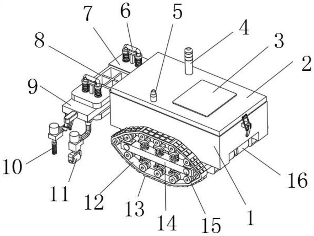
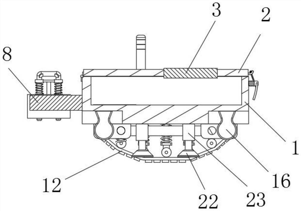
[0042] Example: Reference Figure 1-8 The shown intelligent detection equipment for electromechanical installation faults includes a body 1 .

[0043] The top side of the body 1 is rotatably equipped with an upper cover 2 through a hinge, and the upper cover 2 can be rotated to open, which is convenient for cleaning and maintaining the inside of the body 1 .

[0044] A control panel 3 and a signal receiver 5 are fixedly installed on the top side of the upper cover 2. The signal receiver 5 is arranged to receive signals transmitted by the remote controller and transmit them to the control panel 3 to guide the body 1 to move.

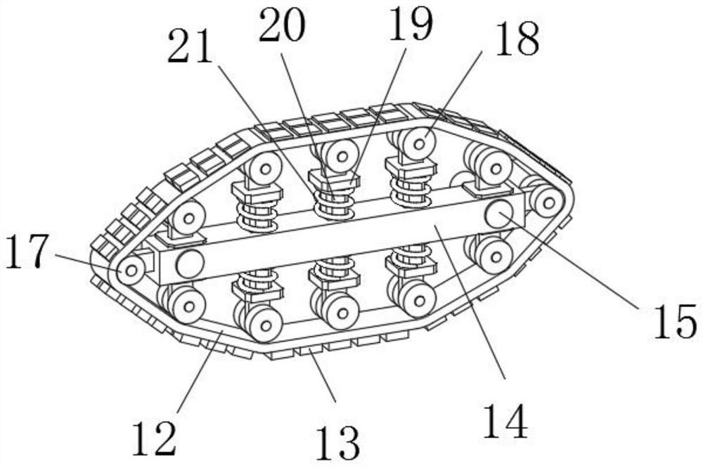
[0045] The bottom side of the body 1 is fixedly installed with two fixed crossbeams 14 through a plurality of fixed rods 15, and a plurality of sliding holes are evenly opened on the two fixed crossbeams 14, and a first square sliding column 20 is correspondingly slidably installed respectively. Both ends of the first square sliding column 20 are rotatab...


PUM


Abstract

The invention discloses electromechanical installation fault intelligent detection equipment, and relates to the technical field of detection equipment, the electromechanical installation fault intelligent detection equipment comprises a machine body, wherein the bottom side of the machine body is fixedly provided with two fixed cross beams through a plurality of fixed rods; the two ends of the two fixed cross beams are rotatably provided with power wheels through rotating shafts; the multiple driven wheels and the multiple power wheels located on the same fixed cross beam are sleeved with the same crawler belt; and a plurality of electromagnets are evenly and fixedly installed on the outer sides of the two crawler belts. The equipment is reasonable in structure and easy to operate, the two crawler belts are arranged on the bottom side of the machine body, the crawler belts are driven to move through the power wheels, the multiple electromagnets generate magnetism through on-off of a circuit and are attracted to metal, the machine body stays on the outer surface of a metal frame located at the high altitude, pictures of the corresponding positions are shot through the camera and transmitted to the control panel, analysis and judgment are made, and whether the bolts are loosened or not is detected.

Description

technical field [0001] The invention relates to the technical field of detection equipment, in particular to an intelligent detection equipment for electromechanical installation faults. Background technique [0002] When installing electromechanical equipment, the most basic part is the connection between bolts and nuts, which is also the part where problems occur most frequently. If the connection is not done properly, such as connecting the bolts and nuts too tightly, the bolts will be affected by mechanical force for a long time. , brings enormous pressure to the metal, resulting in fatigue problems, resulting in damage to the screw teeth, and gradually wears down over time, resulting in the assembly connection between the equipment will be very loose and cannot be carried out normally The work will bring very serious consequences, so the electromechanical equipment needs to be checked regularly after installation. [0003] In the prior art, the image comparison method ...

Claims


Application Information

Patent Timeline
IPC IPC(8): H04N5/225H04N5/232G08C17/02G08B21/18G08B5/36B08B1/00B08B1/04F16F15/067F16M11/04F16M11/42G06T7/00
CPCG08C17/02G08B21/18G08B5/36F16M11/04F16M11/42F16F15/067G06T7/0004H04N23/57H04N23/695B08B1/12B08B1/32
Inventor 刘颜军刘德生
Owner 国网黑龙江省电力有限公司七台河供电公司
Learn More