Circuit board manufacturing method

A manufacturing method and circuit board technology, applied in the field of circuit board manufacturing, can solve the problems of low production yield of circuit boards, poor inter-layer alignment accuracy, poor quality reliability, etc., so as to improve production yield and quality reliability, reduce Alignment deviation, the effect of improving the alignment accuracy between layers

Active Publication Date: 2021-06-08
KINWONG ELECTRONIC TECH (ZHUHAI) CO LTD
View PDF7 Cites 2 Cited by
  • Summary
  • Abstract
  • Description
  • Claims
  • Application Information

AI Technical Summary

Problems solved by technology

[0004] The purpose of the embodiments of the present invention is to provide a method for manufacturing circuit boards to solve the problem of poor interlayer alignment accuracy and large alignment deviations of circuit boards produced in the prior art, resulting in low production yields of circuit boards , technical problems with poor quality and reliability

Method used


Image

  • Circuit board manufacturing method
  • Circuit board manufacturing method
  • Circuit board manufacturing method

Examples


Embodiment Construction

[0037] In order to make the technical problems, technical solutions and beneficial effects to be solved by the present invention clearer, the present invention will be further described in detail below in conjunction with the accompanying drawings and embodiments. It should be understood that the specific embodiments described here are only used to explain the present invention, not to limit the present invention.

[0038] In describing the present invention, it should be understood that the terms "length", "width", "upper", "lower", "front", "rear", "left", "right", "vertical", The orientation or positional relationship indicated by "horizontal", "top", "bottom", "inner", "outer", etc. are based on the orientation or positional relationship shown in the drawings, and are only for the convenience of describing the present invention and simplifying the description, rather than Nothing indicating or implying that a referenced device or element must have a particular orientation,...


PUM


Abstract

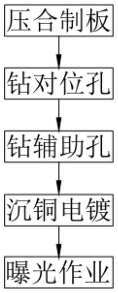
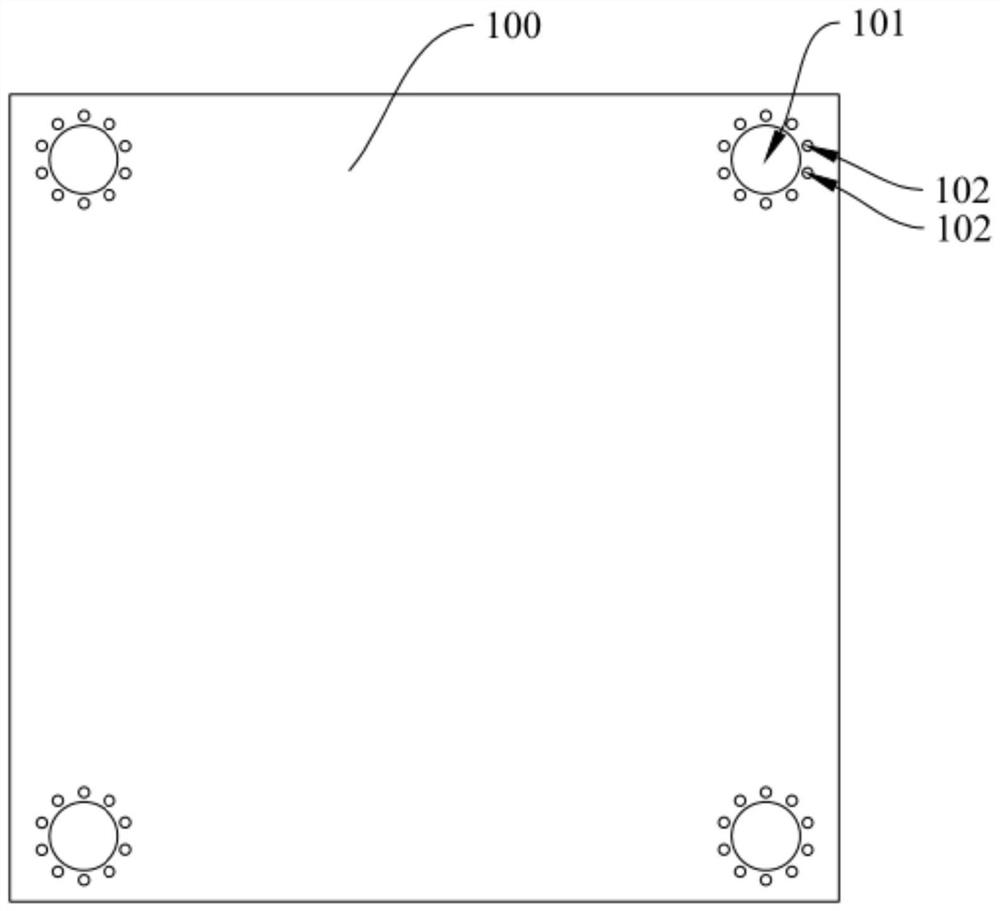
The invention relates to the field of circuit board manufacturing, and provides a circuit board manufacturing method, which comprises the steps of press-fit board manufacturing, alignment hole drilling, auxiliary hole drilling, copper deposition and electroplating, and exposure operation. In the alignment hole drilling step, at least three alignment holes are drilled in the peripheral edge of the plate surface of the pressed blank plate; in the auxiliary hole drilling step, at least one auxiliary structure is drilled on the peripheral side of each alignment hole, and the auxiliary structure comprises a plurality of auxiliary holes arranged in a circumferential array; in the copper deposition and electroplating step, copper deposition and electroplating are carried out on the alignment holes and the auxiliary holes; and in the exposure operation step, the center of each alignment hole is captured as an alignment reference, and exposure treatment is carried out on the surface, deviating from the mother board, of the copper foil. According to the circuit board manufacturing method, by improving the deviation degree of the centers of the alignment holes before and after electroplating, layer-by-layer guarantee is achieved, the interlayer alignment precision is improved, the interlayer alignment precision of the multi-layer circuit board is finally improved, the alignment deviation is effectively reduced, and therefore the production yield and the quality reliability of the multi-layer circuit board can be effectively improved.

Description

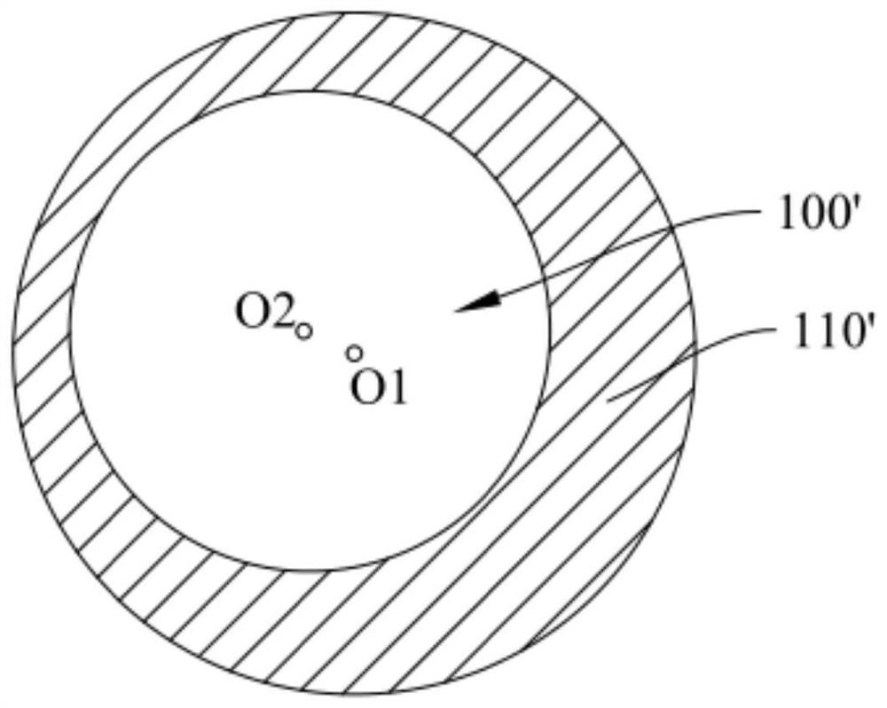
technical field [0001] The invention belongs to the technical field of circuit board manufacturing, and in particular relates to a method for manufacturing a circuit board. Background technique [0002] In the manufacturing process of multi-layer circuit boards, the through holes drilled by the target drilling machine are usually used as alignment holes in related industries, and the exposure operation of the circuit layer is carried out by grabbing the center of the alignment hole in the subsequent process, so as to Make the holes and graphic lines of this line layer correspond to the holes and graphic lines of other line layers. [0003] However, although related industries have improved the inter-layer alignment accuracy to a certain extent by controlling the stability of material expansion and contraction, grasping the variation rules of the process to reduce variation, and improving equipment capabilities, the best inter-layer alignment accuracy in the industry is still...

Claims


Application Information

Patent Timeline
Patent Type & Authority Applications(China)
IPC IPC(8): H05K3/00
CPCH05K3/0047H05K2203/0221
Inventor 张龙刘辉赵斌辉
Owner KINWONG ELECTRONIC TECH (ZHUHAI) CO LTD
Why Eureka
Try Eureka