Special positioning scale for three-dimensional images, surgical navigation system and positioning method of surgical navigation system

A technology of three-dimensional images and positioning rulers, which is applied in the field of surgical positioning, can solve the problems of unfavorable accuracy, improve and increase the perspective of patients during operation time, and achieve the effects of wide applicability, convenient placement and adjustment, and high degree of automation

Inactive Publication Date: 2021-06-11
南京逸动智能科技有限责任公司
View PDF5 Cites 9 Cited by
  • Summary
  • Abstract
  • Description
  • Claims
  • Application Information

AI Technical Summary

Problems solved by technology

[0005] In the above scenario, once the relationship between the image coordinate system and the robot arm coordinate system is established, the robot arm cannot move afterwards. Once one or more paths appear in the plan, the robot arm cannot move to the planned path, and the system can only do it again. , increasing the operating time and the perspective of multiple X-rays of the patient
[0006] When establishing the coordinate mapping relationship between the calibrator and the robot arm, the closer the calibrator and the end of the robot arm are, the better the mapping accuracy will be. However, in actual use, the CTCB machine is mainly a C-arm. In order to prevent interference with the C-arm, it is often The connection distance between the calibrator and the end of the robot arm is relatively large, which is not conducive to the further improvement of the accuracy

Method used


Image

  • Special positioning scale for three-dimensional images, surgical navigation system and positioning method of surgical navigation system
  • Special positioning scale for three-dimensional images, surgical navigation system and positioning method of surgical navigation system
  • Special positioning scale for three-dimensional images, surgical navigation system and positioning method of surgical navigation system

Examples


Embodiment 1

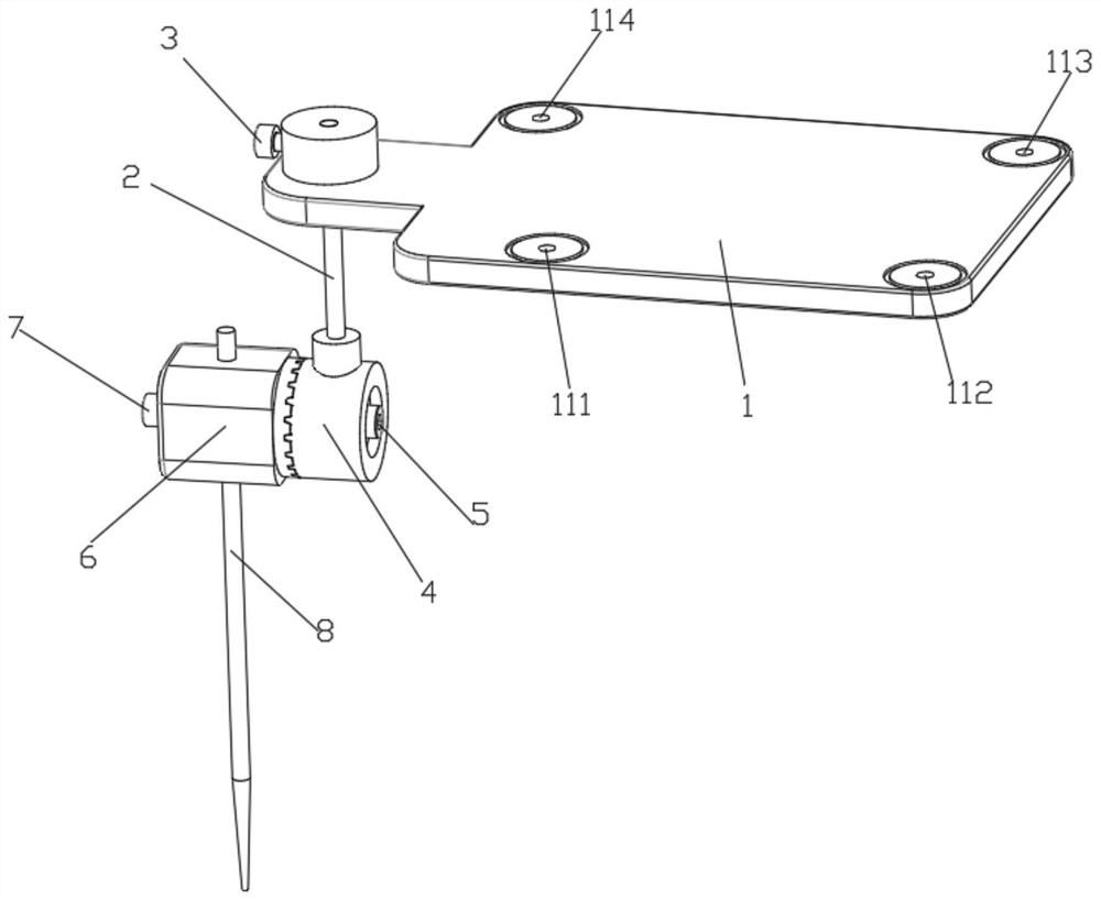
[0030] Such as figure 1 As shown, the present invention proposes a special positioning scale for three-dimensional images: including a calibration device 1, a base 6, a rotating part 4 that cooperates with the base, a calibration device connecting rod 2, and a calibration device for fastening the base and Kirschner wire Fastening screw one 7, one fastening screw two 5 for fastening the base and rotating parts and one fastening screw three 3 for fastening the calibrator and calibrator connecting rod.

[0031] One end of the calibrator 1 is connected to the calibrator connecting rod 2 to realize rotation around the calibrating device connecting rod 2 at any angle, and the surface of the calibrating device 1 is provided with 4 marking points 111, 112, 113 that are not on the same straight line , 114.

[0032] Further, the arrangement shape of each marking point 111 , 112 , 113 , 114 on the surface of the standardizer 1 is anisotropic (for example, the distance between any two ma...

Embodiment 2

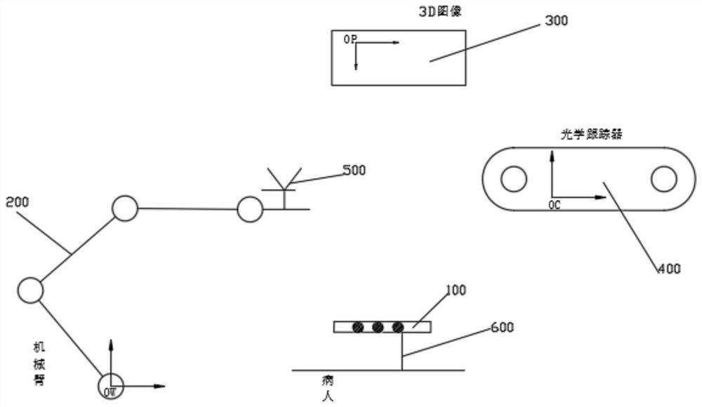
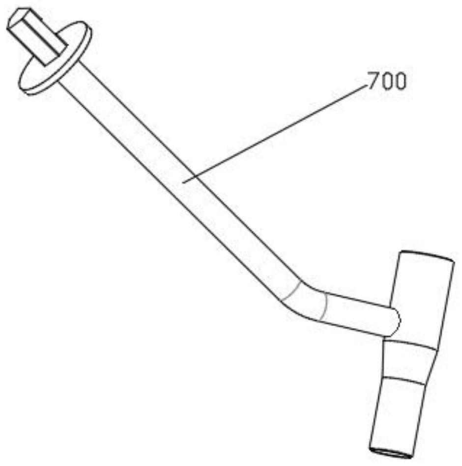
[0037] Such as figure 2 As shown, based on the above-mentioned three-dimensional image-specific positioning scale 1001, the present invention also proposes a surgical navigation system, which includes a three-dimensional image-specific positioning scale 100, a surgical robot 200, a host computer (not shown), a Optical tracker 400 , a robot tracker 500 , a fixed image-specific marker Kirschner wire 600 , a three-dimensional imaging device 300 and a guide 700 . Wherein, the surgical robot 200 is a mechanical arm with at least three translation degrees of freedom and three rotation degrees of freedom. The host computer is connected with the surgical robot 200 and the optical tracker 400 for controlling the movement of the surgical robot 200 and reading the coordinates of the marked points identified by the optical tracker 400 . Robotic tracker 500 is a tool that can be read by optical tracker 400 at the end of surgical robot 200 .

[0038] The optical tracker 400 can identify ...

Embodiment 3

[0042] The positioning method of this embodiment includes the following steps: 1) fixing the 3D image-specific positioning scale on the surface of the surgical site of the patient through Kirschner wires, using a 3D imaging device to scan the 3D image-specific positioning scale and the patient’s surgical site together, and the 3D The imaging device obtains the image of the marked points on the 3D image positioning scale and the patient image, and transmits it to the host computer; at the same time, the optical tracker acquires the coordinates of the 3D image positioning scale and transmits it to the host computer; The marked points in the image are compared with the preset geometric features of the marked points to realize the corresponding identification between the marked points in the three-dimensional image positioning scale and the marking points in the image; Calculate the coordinate transformation relationship between the patient image and the optical tracker according t...


PUM


Abstract

The invention discloses a special positioning scale for three-dimensional images, which can adjust the angle. The special positioning scale for three-dimensional images is characterized by comprising a calibrator, a base, a rotating part matched with the base, a calibrator connecting rod, a first fastening screw used for fastening the base and a kirschner wire, a second fastening screw used for fastening the base and the rotating part and a third fastening screw used for fastening the calibrator and the calibrator connecting rod. One end of the calibrator is designed to be capable of being connected with the calibrator connecting rod, so that the calibrator can rotate by any angle around the calibrator connecting rod, and no less than three marking points are arranged on the surface of the calibrator. The arrangement shape of each mark point on the calibrator surface has anisotropy. The invention further discloses a surgical navigation system and a positioning method thereof. According to the system and the method, the mechanical arm can be moved at will after surgical planning, the defect that the working space range of the mechanical arm is small is avoided, and it is ensured that all surgical paths of a surgical target position can be determined through one-time imaging.

Description

technical field [0001] The invention relates to a special scale for three-dimensional images, a surgical navigation system and a method for positioning using the special positioning scale, and belongs to the technical field of surgical positioning. Background technique [0002] With the widespread application of minimally invasive surgery in recent years and the continuous improvement of the positioning accuracy of instruments or implants during surgery, the auxiliary positioning or surgical navigation system based on medical image guidance has made great progress. The principle of this type of system is divided into the following steps: first, the mapping relationship between the various coordinate systems in the system before the operation is established, that is, the establishment of the surgical target (patient), the three-dimensional medical image established by the CTCB machine, and the respective coordinate systems of the actuators The mapping relationship, this step ...

Claims


Application Information

Patent Timeline
Patent Type & Authority Applications(China)
IPC IPC(8): A61B34/20A61B34/10
CPCA61B34/10A61B34/20A61B2034/105A61B2034/2055A61B2034/2068
Inventor 周振宇罗丹
Owner 南京逸动智能科技有限责任公司
Why Eureka
Try Eureka