Waste residue filtering equipment for sewage treatment

A technology of sewage treatment and filtration equipment, applied in the direction of filtration separation, filtration loop, fixed filter element filter, etc., can solve the problem that sewage waste is not easy to filter and remove, and achieve the effect of reducing work intensity and improving work efficiency

Inactive Publication Date: 2021-06-11
厦门唯晓环保科技有限公司
View PDF0 Cites 1 Cited by
  • Summary
  • Abstract
  • Description
  • Claims
  • Application Information

AI Technical Summary

Problems solved by technology

[0008] Aiming at the deficiencies of the prior art, the present invention provides a waste residue filtering device for sewage treatment, which solves the problem that sewage waste residue is not easy to be filtered and removed

Method used


Image

  • Waste residue filtering equipment for sewage treatment
  • Waste residue filtering equipment for sewage treatment
  • Waste residue filtering equipment for sewage treatment

Examples


Embodiment 1

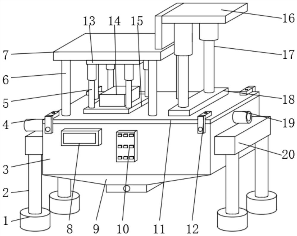
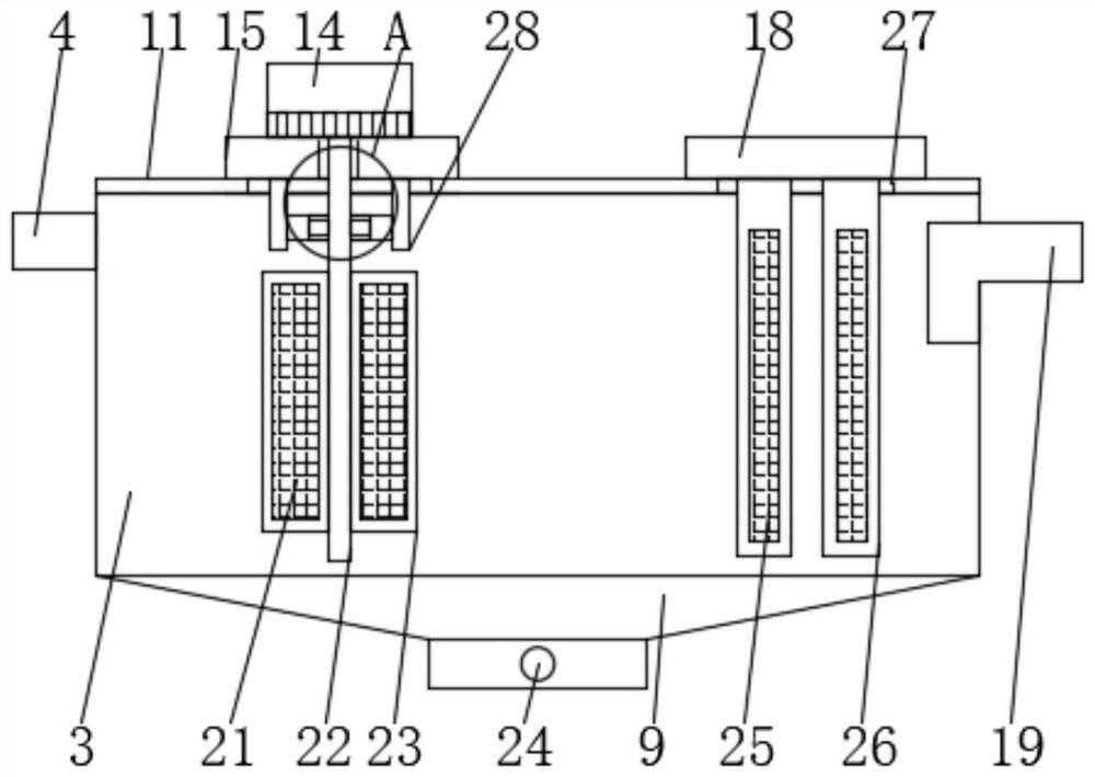
[0033] Such as Figure 1-4 As shown, the embodiment of the present invention provides a waste residue filtering device for sewage treatment, including a box body 3, the upper end of the box body 3 is provided with a cover plate 11, and the left side of the middle part of the upper end of the cover plate 11 is provided with a second port 31, On the left side of the upper end of the cover plate 11 and with respect to the surroundings of the second port 31, a support rod 6 is fixedly connected, the upper end of the support rod 6 is fixedly connected with a support plate 7, and a first electric pusher is arranged around the lower end of the support plate 7. Rod 5, the side of the first electric push rod 5 is fixedly connected with a fixed block 13, the upper end of the fixed block 13 is connected with the lower end of the support plate 7, and the lower end of the first electric push rod 5 is fixedly connected with the second port 31 There is a first sealing plate 15 to adjust the ...

Embodiment 2

[0037] The difference between this embodiment and the first embodiment is that the first electric push rod 5 and the second electric push rod 17 can be replaced with air cylinders, so that the first sealing plate 15 and the second sealing plate can be adjusted in a pneumatic way. 18' use height for adjustable use.

Embodiment 3

[0039] The difference between this embodiment and the first embodiment is that the U-shaped block 28 is replaced by a sleeve, and the middle part of the sleeve is provided with a rotating hole 29, and the upper end of the sleeve and the outer end of the rotating hole 29 are connected to the first sealing plate 15. Fixedly connected, the rotating rod 22 penetrates the sleeve, and the inner wall of the sleeve is fixedly connected with a buffer pad 30 relative to the outer surface of the rotating rod 22. The buffer pad 30 is used to buffer the rotating rod 22 without affecting the rotation of the rotating rod 22. In use, the sleeve can extend the buffer protection distance of the rotating rod 22, thereby reducing the degree of shaking of the rotating rod 22.

[0040] Working principle: U-shaped tubes 9 are deposited at the lower end of the box body 3 to effectively collect the depositable waste residue, and the use height of the first sealing plate 15 is adjusted by the first elec...


PUM


Abstract

The invention provides waste residue filtering equipment for sewage treatment, and relates to the technical field of sewage treatment. The waste residue filtering equipment for sewage treatment comprises a box body, a cover plate is arranged at the upper end of the box body, a second through opening is formed in the left side of the middle of the upper end of the cover plate in a penetrating mode, supporting rods are fixedly connected to the left side of the upper end of the cover plate and correspond to the periphery of the second through opening, and a supporting plate is fixedly connected to the upper ends of the supporting rods; first electric push rods are arranged on the periphery of the lower end of the supporting plate, a first sealing plate is fixedly connected to the lower ends of the first electric push rods relative to the second through opening, a motor is arranged in the middle of the first sealing plate in a penetrating mode, a motor shaft extends from the lower end of the motor, and a rotating rod is fixedly connected to the lower end of the motor shaft; and a first storage frame is fixedly connected to the outer surface of the rotating rod and located in the box body, and a first filter screen is arranged in the middle of the first storage frame. The waste residues in the sewage can be effectively and efficiently filtered out.

Description

technical field [0001] The invention relates to the technical field of sewage treatment, in particular to waste residue filtering equipment for sewage treatment. Background technique [0002] Sewage treatment is the process of purifying sewage to meet the water quality requirements for discharge into a certain water body or reuse. Sewage treatment is widely used in various fields such as construction, agriculture, transportation, energy, petrochemical, environmental protection, urban landscape, medical treatment, catering, etc., and it is also increasingly entering the daily life of ordinary people. [0003] According to the classification of sewage sources, sewage treatment is generally divided into production sewage treatment and domestic sewage treatment. Production sewage includes industrial sewage, agricultural sewage and medical sewage, etc., while domestic sewage is sewage produced in daily life, which refers to a complex mixture of various forms of inorganic and org...

Claims


Application Information

Patent Timeline
Patent Type & Authority Applications(China)
IPC IPC(8): B01D36/02B01D36/04B01D29/96B01D33/15B01D33/80
CPCB01D29/96B01D33/15B01D33/803B01D36/02B01D36/04
Inventor 曾艺燕
Owner 厦门唯晓环保科技有限公司
Why Eureka
Try Eureka