

Coaxial multi-output steering engine and output method
A multi-output and steering gear technology, applied in the field of coaxial multi-output steering gear and coaxial multi-output, can solve problems such as inability to sense angle changes, complex structure, and large interference effects, so as to improve stability and reliability, Simplified overall structure design and compact space layout
- Summary
- Abstract
- Description
- Claims
- Application Information
AI Technical Summary
Problems solved by technology
Method used
Image

Examples
Embodiment 1
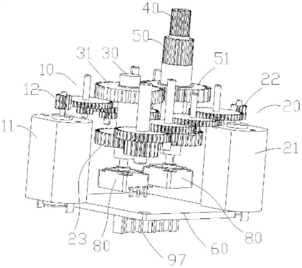
[0071] The present invention provides a coaxial multi-output steering gear. It should be noted that: the multi-output described in this application can be understood as at least two outputs, which is different from the single-axis single-output steering gear in the prior art; the coaxial can be It is understood that the centerlines of the output shafts are on the same axis. In this embodiment, as attached Figure 1-8 As shown, what is disclosed is the coaxial dual output steering gear in an embodiment of the coaxial dual output steering gear.
[0072] In order to construct the coaxial dual-output steering gear in this embodiment, it includes a first drive deceleration mechanism 10, a second drive deceleration mechanism 20, a transmission shaft 30, a first output shaft 40, a second output shaft 50, a control board 60, a first A feedback component and a second feedback component.
[0073] Wherein, the first drive reduction mechanism 10 includes a first drive motor 11 and a fir...
Embodiment 2
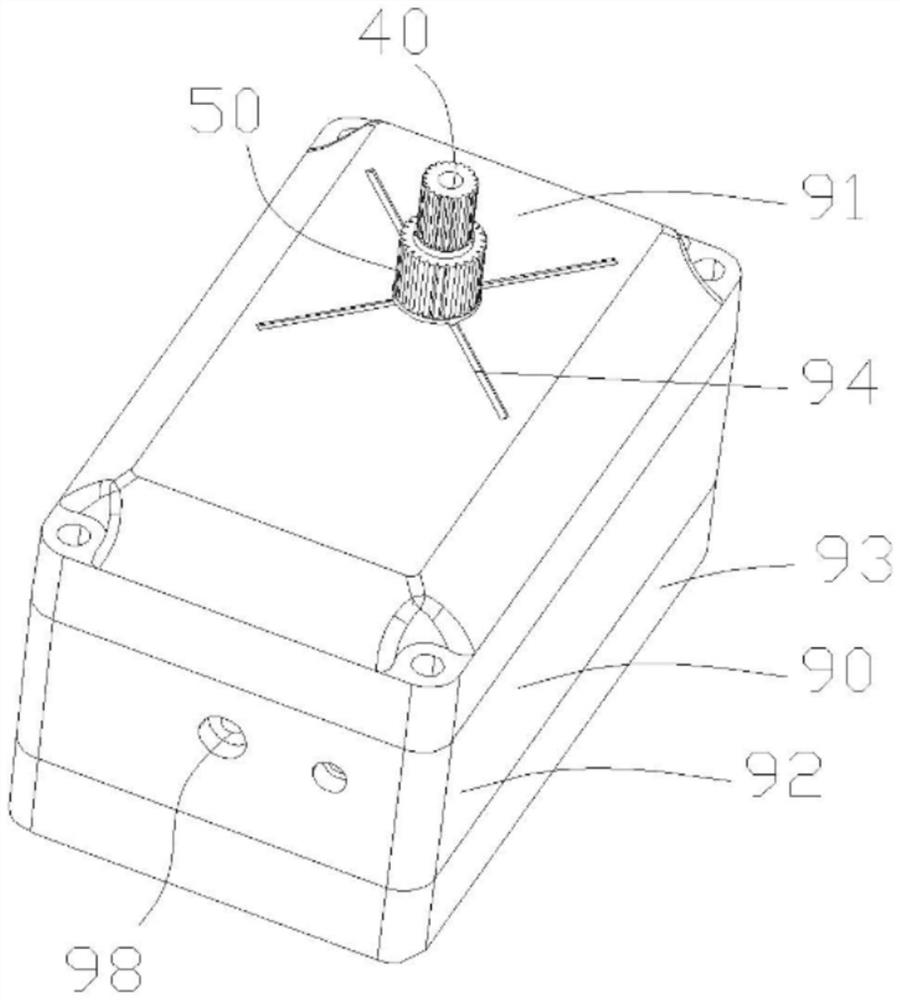
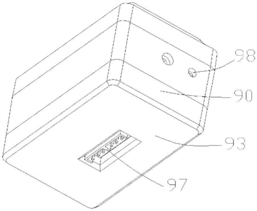
[0091] On the basis of embodiment one, refer to the attached Figure 1-8 , in order to realize the integrated installation of the steering gear, the steering gear also includes a rectangular housing 90, which is equivalent to the installation carrier of each component. In this embodiment, the housing 90 includes an upper housing 91, a middle housing 92, and a lower housing 93 that are fitted and connected, and the upper housing 91, the middle housing 92, and the lower housing 93 are assembled by long screws located at four corners. connected into one.
[0092] Wherein the upper casing 91 is provided with a through hole (not shown) for the coaxial first output shaft 40 and the second output shaft 50 to protrude for external connection, and the peripheral part of the outer wall of the through hole is provided with a mechanical assembly reference mark 94 . The mechanical assembly reference mark 94 may be one of a cross scale mark and a circular scale ring mark arranged along th...
Embodiment 3
[0099] Different from Embodiments 1 and 2, in this embodiment, refer to the attached Figure 9 , the first feedback assembly includes a first magnet 100 and a first magnetic sensor 101 , the first magnet 100 is installed at the center of the bottom end surface of the first output shaft 40 , and the first magnetic sensor 101 is correspondingly installed on the control board 60 . In order to realize the installation of the first magnetic sensor 101 , the control board 60 has an installation position directly below the center of the bottom end surface of the first output shaft 40 for installing the first magnetic sensor 101 . Therefore, when the first output shaft 40 rotates, the first magnetic sensor 101 can always obtain the rotation information, especially the rotation angle information, of the first magnet 100 located at the center of the bottom end surface of the first output shaft 40 .
[0100] After the first magnetic sensor 101 is electrically connected to the control boa...
PUM
 Abstract
Description
Claims
Application Information