
Ejection mechanism and injection mold

A technology of injection mold and ejection mechanism, which is applied in the field of ejection mechanism and injection mold, can solve the problems of low efficiency, long production cycle, high cost, etc., and achieve the effect of reducing cost and improving production efficiency

Pending Publication Date: 2021-06-11
南通银宝山新科技有限公司
View PDF0 Cites 2 Cited by
  • Summary
  • Abstract
  • Description
  • Claims
  • Application Information

AI Technical Summary

Problems solved by technology

[0003] However, the molded parts in the mold cavity are generally connected with nozzles. Generally, after the molded parts are removed, the nozzles on it are manually cut off. This production method has a long production cycle and low efficiency. more expensive to manufacture

Method used


Image

  • Ejection mechanism and injection mold
  • Ejection mechanism and injection mold
  • Ejection mechanism and injection mold

Examples


Embodiment Construction

[0040] The following will clearly and completely describe the technical solutions in the embodiments of the present invention with reference to the accompanying drawings in the embodiments of the present invention. Obviously, the described embodiments are only part of the embodiments of the present invention, not all of them. Based on the embodiments of the present invention, all other embodiments obtained by persons of ordinary skill in the art without making creative efforts belong to the protection scope of the present invention.

[0041] It should be noted that all directional indications (such as up, down, left, right, front, back...) in the embodiments of the present invention are only used to explain the relationship between the components in a certain posture (as shown in the accompanying drawings). Relative positional relationship, movement conditions, etc., if the specific posture changes, the directional indication will also change accordingly.

[0042] In addition,...


PUM


Abstract

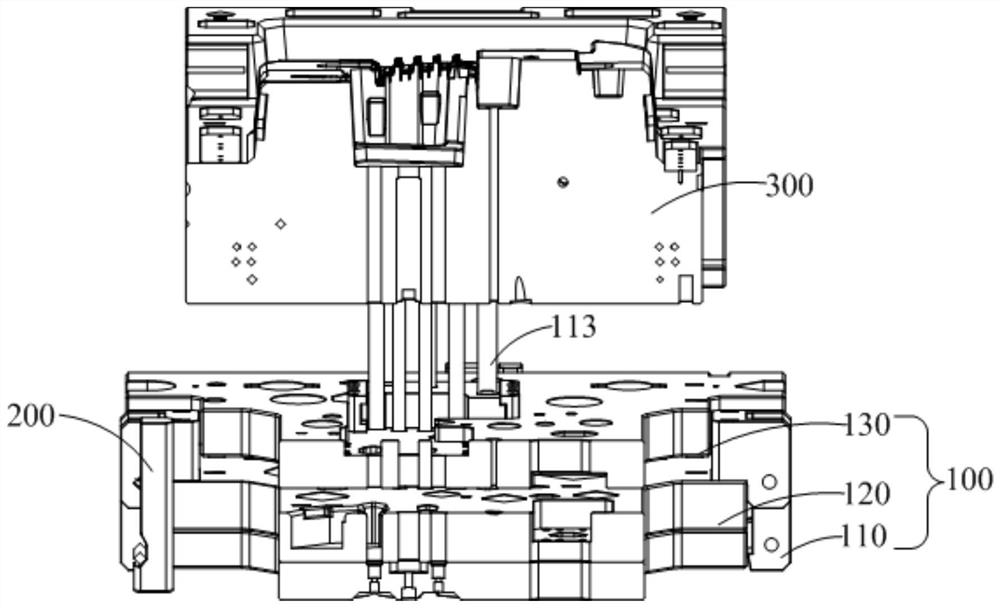
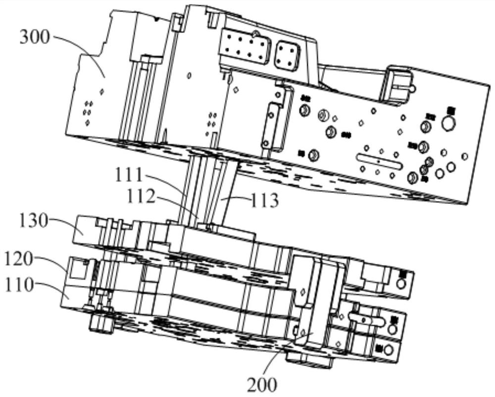
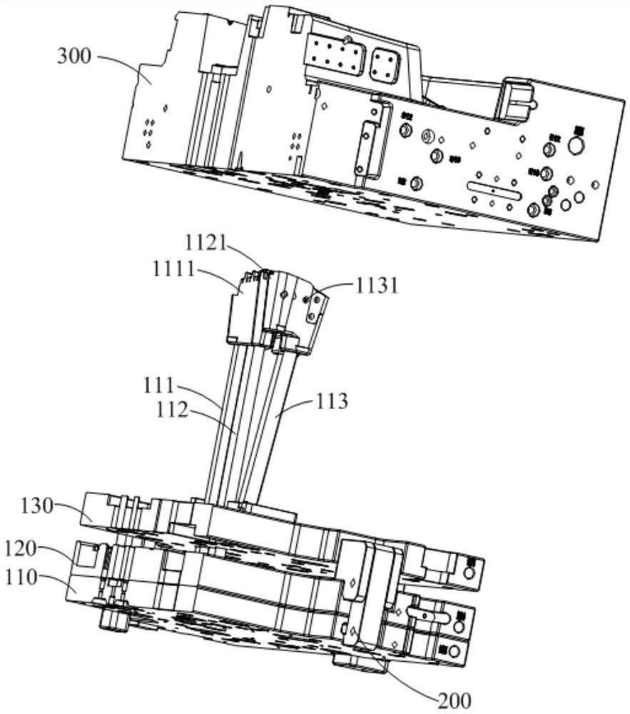
The invention discloses an ejection mechanism and an injection mold. The ejection mechanism comprises a fixing plate, an ejector pin assembly and a buckling machine assembly; the ejector pin assembly is movably arranged on the fixing plate and is in driving connection with an oil cylinder; the buckling machine assembly is connected with the ejector pin assembly and is used for limiting the ejector pin assembly when the injection mold is opened or closed; when the injection mold is in a mold opening state, under driving of the oil cylinder, the ejector pin assembly is separated from the buckling machine assembly to cut off a water gap of a formed product when the ejector pin assembly is ejected out of the initial position to the first preset position. The ejection structure of the mold is improved, the functions of ejection and automatic cutting of the water gap are achieved, the production efficiency of products is improved, and the production and manufacturing cost is reduced.

Description

technical field [0001] The invention relates to the technical field of molds, in particular to an ejection mechanism and an injection mold. Background technique [0002] In the mold design, the ejector mechanism is an important part of the mold, and its main function is to eject the molded parts in the mold cavity or adhered to the core. In general, the ejector mechanism applies thrust to the fixed plate, and drives one or more ejector pins or thimbles against the formed part through the fixed plate, and ejects the formed part formed in the mold cavity or adhered to the main core. In this way, one molding process is completed and the next molding process is started. In the injection machine, the ejector mechanism is usually installed on the side of the movable mold. Or a molded part adhered to the main core on the male side. [0003] However, the molded parts in the mold cavity are generally connected with nozzles. Generally, after the molded parts are removed, the nozzles...

Claims


Application Information

Patent Timeline
Patent Type & Authority Applications(China)
IPC IPC(8): B29C45/40B29C45/38
CPCB29C45/4005B29C45/38
Inventor 韩在忠陈林强宋勇
Owner 南通银宝山新科技有限公司
Learn More