
Variable pitch propeller

A variable-pitch propeller and propeller root technology, which is applied to propellers, aircraft parts, transportation and packaging, etc., can solve the problems of complex structure and action, matching problems of connection parts, high cost of blades, etc., and achieve simple and compact structure and guaranteed connection strength , The effect of simple assembly process

Pending Publication Date: 2021-06-11
安徽羲禾航空科技有限公司
View PDF0 Cites 2 Cited by
  • Summary
  • Abstract
  • Description
  • Claims
  • Application Information

AI Technical Summary

Problems solved by technology

The problem with the traditional propeller margin control device is that: on the one hand, the variable pitch power transmission traditionally relies on the bevel gear transmission structure, or the connecting rod transmission structure, etc., without exception, there are defects in the structure and action. Maintenance and repair are very complicated; on the other hand, for the connection structure between the traditional hub and the blade, only a single bearing is used to ensure that the blade can rotate relative to the hub; however, the blade is working At the same time, it also needs to bear a huge centrifugal force. The centrifugal force is applied to the connection between the blade and the hub. After a long time, it is easy to cause problems in the connection, which will have a great impact on the normal and reliable operation of the propeller.
Obviously, the above-mentioned existing connection structure is complex, and the entire manufacturing process involves many assembly processes and furnace curing processes, resulting in a high cost of the blade, which brings many troubles to the actual production and operation and later maintenance.

Method used


Image

  • Variable pitch propeller
  • Variable pitch propeller
  • Variable pitch propeller

Examples


Embodiment Construction

[0059] For ease of understanding, here in conjunction with accompanying drawing, the concrete structure of the present invention and working mode are further described as follows:

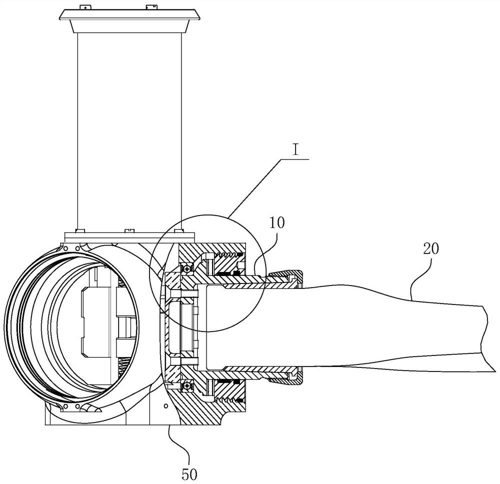
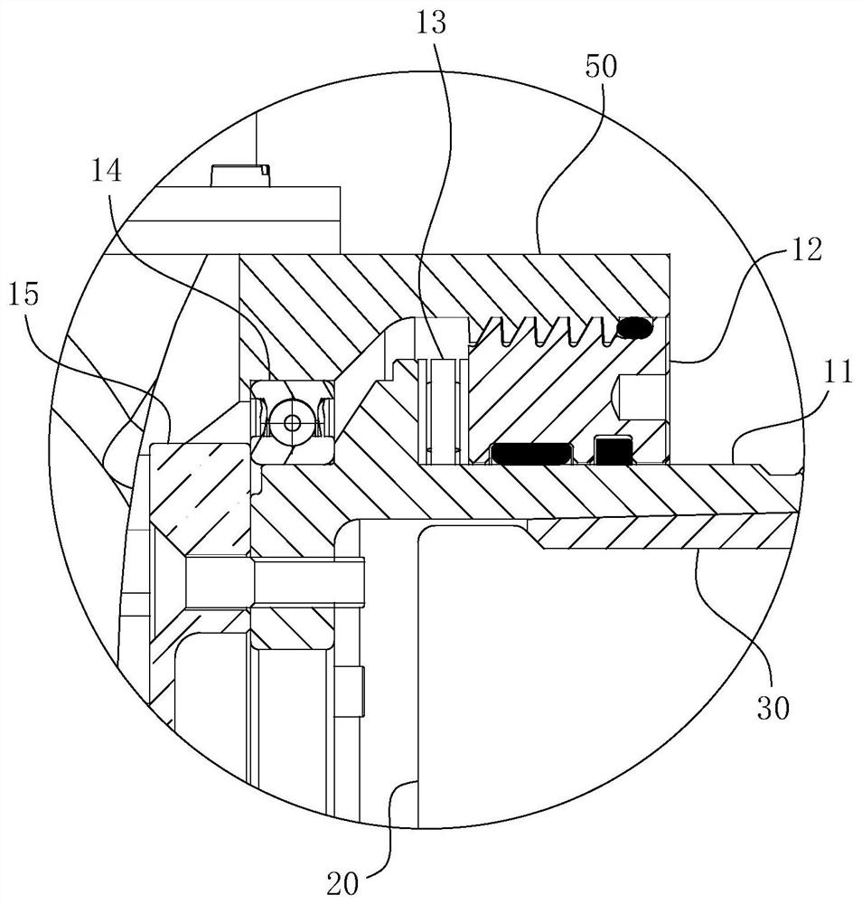
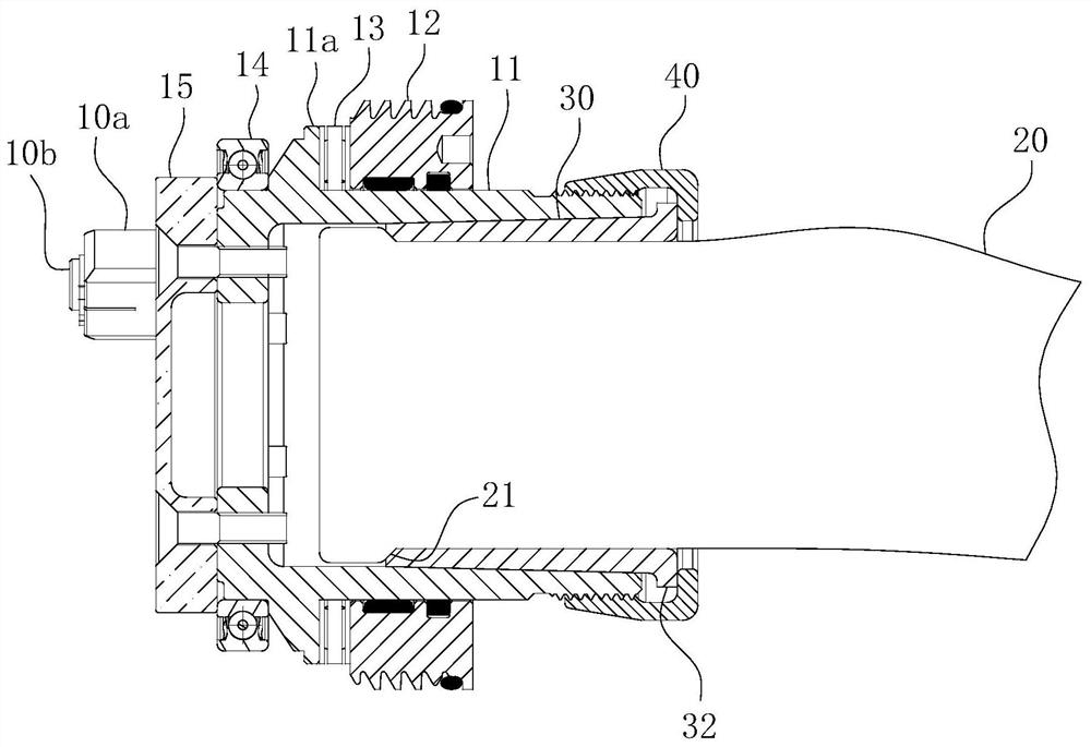
[0060] The specific structure of the present invention is as Figure 1-17 As shown, it is mainly based on the variable-pitch rotary assembly that realizes the controllable rotation of the blade relative to the hub 50, supplemented by a variable-pitch drive assembly that drives the variable-pitch rotary assembly to generate action, and an induction that automatically switches the action mode of the variable-pitch actuator assembly. Components, thereby jointly forming three major modules of the present invention. For easier understanding, the variable pitch rotary assembly can be regarded as mainly aimed at the change of the blade, the variable pitch drive assembly is mainly aimed at the change of the inner structure of the propeller hub 50 , and the induction component is mainly aimed at the change ...


PUM


Abstract

The invention belongs to the technical field of propellers, and particularly relates to a free variable pitch propeller. The variable pitch propeller comprises a propeller hub and blades which are rotatably matched in an assembly cavity of the propeller hub through a propeller root part, and is characterized in that the propeller root part comprises a sleeve-shaped propeller root support, an annular bulge, a radial bearing and a rotary connecting seat are coaxially and sequentially arranged on the propeller root support from back to front, and the outer ring surface of the rotary connecting seat is fixed on the assembly cavity; the inner ring surface of the rotary connecting seat and the paddle root support form rotary fit with the rotary axis coaxial with the axis of the paddle root support, and the two ends of the radial bearing abut against the front side shaft shoulder of the annular protrusion and the rear side ring surface of the rotary connecting seat respectively. The connecting strength of the blades and the propeller hub can be effectively guaranteed while the normal rotation function of the blades relative to the propeller hub is guaranteed, and the propeller has the advantages of being simple and compact in structure, concise in assembly process and low in cost.

Description

technical field [0001] The invention belongs to the technical field of propellers, in particular to a freely variable pitch propeller. Background technique [0002] The propeller is a key component of the aircraft, and the propeller is used to convert the rotation of the motor or engine shaft of the aircraft into propulsion, thereby providing the aircraft with flight power. The propeller pitch control device is to control the propeller to work at the best blade angle under various working conditions of the engine and the aircraft, so as to achieve the best working efficiency of the propeller. Because the flight environment of the aircraft is very complex, it is a permanent subject to study the pitch control device of the propeller so that it can control the blade angle more accurately and achieve the best output efficiency of the propeller. The problem with the traditional propeller margin control device is that: on the one hand, the variable pitch power transmission tradit...

Claims


Application Information

Patent Timeline
IPC IPC(8): B64C11/06B64C11/32
CPCB64C11/06B64C11/32
Inventor 盛应彤刘传超赵昌霞周星
Owner 安徽羲禾航空科技有限公司
Learn More