Outdoor clothes hanger based on air flow

A technology of air flow and clothes hanger, which is applied to washing devices, textiles and papermaking, household appliances, etc., can solve the problems of shaking, accelerated air drying, water loss, etc., and achieve better drying effect and faster drying speed

Inactive Publication Date: 2021-06-11
刘小雪
View PDF0 Cites 0 Cited by
  • Summary
  • Abstract
  • Description
  • Claims
  • Application Information

AI Technical Summary

Problems solved by technology

[0006] The technical problem to be solved in the present invention is to provide an outdoor clothes drying rack based on gas flow, one of which is to have the function of automatically adjusting the angle and solve the problem of the light-receiving area of ​​clothes in drying; the other purpose is to solve the problem of fast drying of clothes In order to achieve the effect of accelerating air-drying, another purpose is to have a shaking function to facilitate water loss, which is conducive to the drying speed of clothes, and at the same time solves the problem of clothes being contaminated with dust

Method used


Image

  • Outdoor clothes hanger based on air flow
  • Outdoor clothes hanger based on air flow
  • Outdoor clothes hanger based on air flow

Examples


Embodiment 1

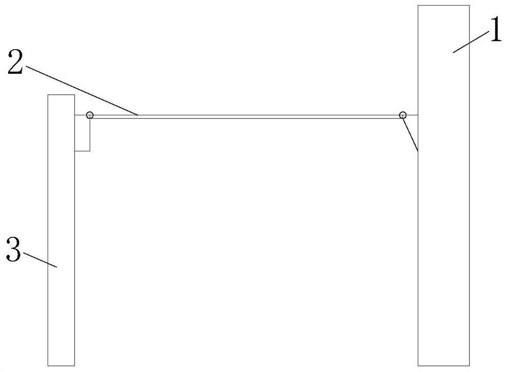
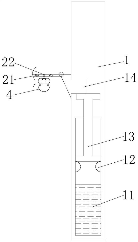
[0025] Such as figure 1 - Figure 6 As shown, the present invention provides an outdoor clothes drying rack based on gas flow, which includes an adjustment column 1 and a clothes drying rod 2 .

[0026] In this embodiment, a low-melting evaporative liquid 11 is provided under the inside of the adjusting column 1, and stoppers 12 are fixedly connected to both sides of the inner wall of the adjusting column 1, and a push rod 13 is arranged on the top of the stopper 12, and the push rod 13 An adjustment block 14 is arranged on the top, and the end of the adjustment block 14 away from the adjustment column 1 is rotatably connected to the clothes-drying pole 2, and the other end of the clothes-drying pole 2 is rotatably connected to the support column 3, and the interior of the clothes-drying pole 2 is provided with a plurality of magnetic blocks 21, and the adjacent side of the magnetic block 21 is set to the same pole, and the adjacent place of every two magnetic blocks 21 is pr...

Embodiment 2

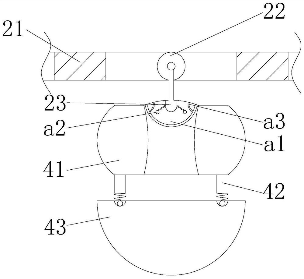
[0028] Such as Figure 3-5 As shown, on the basis of Embodiment 1, the present invention provides a technical solution: the outer wall of the movable ball 22 is provided with a rotating rod 23, and the bottom of the rotating rod 23 is movably installed with a swing mechanism 4, and the swing mechanism 4 includes a first connecting block 41 and the second connection block 43, the two ends of the bottom of the first connection block 41 are symmetrically provided with connection columns 42, the bottom of the connection column 42 is fixedly connected with a spring b1, and the bottom of the spring b1 is fixedly connected with a block b2, the second connection block The two ends of the top of 43 are symmetrically provided with card slots c1, the first connecting block 41 and the second connecting block 43 are movably connected by the provided card block b2 and the card slot c1, and the top of the first connecting block 41 is provided with a first cavity a1, the outer wall of the bot...

Embodiment 3

[0030] Such as Figure 3-6 As shown, on the basis of Embodiment 1 and Embodiment 2, the present invention provides a technical solution: preferably, a second cavity c2 is opened inside the second connecting block 43, and the bottom of the inner wall of the second cavity c2 The corrugated setting is adopted. There are multiple rolling balls c3 inside the second cavity c2. There are five rolling balls c3 with the heaviest weight at the center. Under the obstruction of the corrugations, they hit the lever c4 in stages, and the impact force is stronger. The inner right end of the second cavity c2 is movably installed with a lever c4, the bottom of the second connecting block 43 is provided with a third cavity c5, the left end of the third cavity c5 is fixedly connected with a solid ball c6, and the surface of the right end of the solid ball c6 is fixed. A tubular airbag c8 is connected, the right end of the tubular airbag c8 is closely connected with a spherical airbag c7, the bot...


PUM


Abstract

The invention discloses an outdoor clothes hanger based on gas flow, and relates to the technical field of household appliances. The outdoor clothes hanger comprises an adjusting column and a clothes airing rod; low-melting-point evaporated liquid is arranged at the lower part in the adjusting column; two sides of the inner wall of the adjusting column are fixedly connected with stop blocks; the top of each stop block is provided with a push rod, and the top of each push rod is provided with an adjusting block; the end, away from the adjusting column, of each adjusting block is rotationally connected with the clothes airing rod; the other end of the clothes airing rod is rotationally connected with a supporting column; a plurality of magnetic blocks are arranged in the clothes airing rod; the adjacent sides of the magnetic blocks are arranged to be homopolar; and a movable ball is arranged at the adjacent position of every two magnetic blocks. The low-melting-point evaporated liquid and the adjusting block are combined, the angle of the clothes airing rod is conveniently and automatically adjusted under the change of illumination intensity, and clothes are aired in a staggered mode; a first connecting block and a second connecting block are combined, the clothes hanger is shaken, and evaporation of moisture of the clothes is accelerated; and meanwhile, dust contaminated on the clothes is shaken off, and the dust shaking work when the clothes are collected is omitted.

Description

technical field [0001] The invention relates to an outdoor clothes drying rack, relates to the technical field of household appliances, in particular to an outdoor clothes drying rack based on gas flow. Background technique [0002] Clothes rack is one of the requisite daily necessities in people's daily life. Existing drying racks can be divided into indoor drying racks and outdoor drying racks. Outdoor drying racks can enjoy rapid drying and sterilization under sunlight. At present, most outdoor drying racks for household use can only be hung in parallel or manually hung at different heights for dislocation drying. Clothes, in windy weather, the clothes to be dried are easily contaminated with dust, and every piece of clothes has to be dusted when collecting clothes, which is time-consuming and laborious, and in this kind of weather, the drying speed of clothes is slow. [0003] There are following problems at prior art: [0004] 1. In the prior art, there is a problem t...

Claims


Application Information

Patent Timeline
Patent Type & Authority Applications(China)
IPC IPC(8): D06F57/06
CPCD06F57/06
Inventor 孙全胜
Owner 刘小雪
Why Eureka
Try Eureka